Regardless of the technology used, the basic design of the inverter is clear and very similar. The core is the process of converting DC voltage (photovoltaic modules) into AC voltage (which can be connected to the grid). In the process of the transition, the positive and negative poles of the direct current are continuously switched, thereby forming an alternating current with a change in direction. Therefore, the key component of the inverter is the bridge switch (transistor component, see Figure 1: a)). One side of this switch bridge is connected to the input DC power supply and the other side is connected to the AC grid. During operation, only two opposite switches can be turned off at the same time. If the switching speed of the switching bridge is set to be the same as the grid frequency, the output side of the bridge can theoretically be connected to the grid. However, since the current thus output is a square wave and the intensity does not change, it is necessary to mount an inductor having an iron core at the output to control the output current into a sine wave shape. The breaking of the bridge is performed using a pulsed process to form a smaller current component associated with the pulse. Such a current component can control the current of the inductor. The frequency of the pulse is generally 20KHz, so that a 50Hz current can be formed completely, see Figure 1: b). For photovoltaic inverters, there is another very important device that cannot be missed: the capacitor at the input, see Figure 1: c). The function of the capacitor is to store electrical energy, ensuring that the current from the generator side is consistently supplied to the bridge switch and enters the grid through a bridge that changes synchronously with the grid frequency. Only when the capacity of the input capacitor is large enough can the continuous and normal operation of the photovoltaic power generation system be ensured. Figure 2 depicts the basic functions of an inverter that can be used for direct grid connection. However, in practical applications, the range of input voltage has certain limitations. For grid-connected power generation applications, the input voltage must be higher than the peak voltage of the grid at any time. When the effective value of the grid voltage is 250V, the minimum voltage on the power supply side that meets the requirements for normal grid connection should be 354V. Unlike the basic design of a standard inverter, direct grid-connected inverters have many ways to adjust or boost the input voltage range. Commonly used inverter technology solutions and structures are different: The inverter topology mentioned above differs not only in terms of electrical isolation, but also in terms of achievable efficiency and dependence on voltage. Therefore, there is no uniform formula to define which inverter design is the best design, and the user must consider the specific inverter characteristics. At present, as long as the photovoltaic power station is designed reasonably, it can operate economically. Transformerless inverters that are directly integrated into the grid are receiving increasing attention due to their low cost and high efficiency. However, the technology is still considered "problematic." This will be examined and illustrated below. The transformer converts electrical energy into magnetic energy and converts the magnetic energy into electrical energy. The energy loss caused by the electrical isolation device installed between the input and output can reach 1% or even 2%. Therefore, the transformerless inverter operates at a higher efficiency than the transformer inverter. There are many other advantages to this technique, such as low material consumption and light weight. All in all, transformerless inverters are relatively small in size, light in weight, and relatively inexpensive, and in many respects are more advantageous than transformer-type inverters. Although the operation and safety of photovoltaic power plants do not require electrical isolation measures, the following aspects should be considered when designing direct grid-connected inverters. The voltage from the PV modules is converted in a high frequency (20 kHz) process. The high frequency voltage should be equal to the peak value of the grid voltage; these voltages are considered to be interference inside the inverter, and the filter can block these interferences and prevent them from entering the grid. . But in theory, it is impossible to prevent the DC component from the power generation side from entering the AC grid. Thus, depending on the architecture of the inverter used, there will also be different DC voltage components to ground in the AC output. If the solar cell and/or its terminals have an AC voltage to ground, a “leakage current†will be generated that flows through the parasitic capacitance to the battery ground. Below we take the Sunny Boy 2100TL and the Sunny Boy 5000TL HC as examples. As shown in FIG. The operation of these two inverters produces time-dependent potentials in their electronics, and their PV modules have different voltages to ground. The Sunny Boy 2100TL uses an H-bridge structure, and the voltage applied to the PV modules is half the rms voltage of the grid. The multi-string inverter SB5000TL HC uses a capacitor half-bridge structure. The centerline of the bridge is directly connected to the centerline of the grid. The result of this is that the generated ground voltage is only a low voltage value of 50 Hz, and its component is only a small part of the grid voltage, which is only equivalent to the voltage ripple amount in the transformer topology. In addition to grid voltage boost considerations, the magnitude of the leakage current is also dependent on the parasitic capacitance of the photovoltaic component, which is related to the cell area and the distance between the component and the bezel. Therefore, regarding the leakage current situation, the structure of the inverter and the size of the photovoltaic module should be carefully considered when designing the system. The larger the area, the smaller the distance between the battery and the frame of the photovoltaic module, and the greater the leakage current generated. The leakage current value of the frameless structure photovoltaic module is very low. However, an amorphous battery mounted on a stainless steel foil generates a large leakage current. External conditions also have an effect on the leakage current, so there is inevitably some fluctuation. If a precipitate or cleaning solution wets the photovoltaic module, the leakage current increases; the electronic component in these liquids shortens the distance between the battery and the battery, causing an increase in leakage current. In summary, the leakage current of a PV module during operation (normally) depends on many operating conditions and is not measured by a fixed value. Taking an H-bridge inverter (such as the Sunny Boy 2100TL) as an example, the leakage current value of the photovoltaic module during operation is in the range of 1-30 mA/KWp. In photovoltaic power plants for grid-connected applications, only photovoltaic modules with reliable insulation of the cell and frame can be used. The components should have double or super strong insulation measures, and the system pressure resistance of the PV modules should be fully considered to ensure that the surface of the components can be touched even when the PV system is in operation without danger. At present, all PV modules can achieve Class II protection, and there are no strict restrictions on the selection. As described above, for a transformerless inverter, the voltage on the photovoltaic module during operation may be a synchronous voltage value superimposed on the AC grid. When the surface of the component is touched, a fault current to ground may be generated. If the insulation of the component is good enough, it is generally difficult to have such current generation. However, the intensity of the fault current discharge will increase with some conditions, such as a shortened distance of the photovoltaic cell (in this case, the thickness of the transparent glass or plastic plate is reduced), an increase in the contact area, and the like. For example, due to the conductive material contained in the liquid cleaning the photovoltaic module, the conductive area is enlarged, resulting in an unexpected fault current. In this case, although the dangerous current cannot be detected in advance, there is a certain danger if an accident occurs. In order to avoid the safety hazards caused by this (similar to sudden falling off the ladder, etc.) and to avoid danger, users should follow the following steps when constructing a photovoltaic grid-connected power generation system: 1) Connect the frame of the PV module and other conductive gas parts to the ground wire 2) Disconnect the inverter from the grid when performing maintenance on the system or cleaning the PV modules With these protective measures, personnel safety can be fully guaranteed. Designed precision transformerless inverters with additional protection, even if it exceeds the safety standards required for electrically isolated inverters, there is no need to worry about safety. In this type of inverter, the DC or AC leakage current that may be generated by the component is continuously monitored. Once the fault current (greater than 30 mA) is generated, the inverter immediately disconnects from the grid. However, the monitoring of fault currents in real-world applications is more complicated than simply monitoring the magnitude of leakage currents. The leakage current changes at any time during the system operation, and the current value is not known before the grid connection. Therefore, the insulation resistance of the photovoltaic module is detected each time the inverter is connected to the grid. Only when the insulation resistance exceeds the required resistance value (greater than 1M ohm) can it be proved that no fault current is injected into the grid, and the grid can be connected at this time. Therefore, the identification of the fault current is not only known by monitoring the increase in the leakage current but also by measuring the rate of change of the current. All fault current monitoring devices must have leakage current detection (dual), and each monitoring system must be able to independently identify the fault current. In this way, personal safety will be more protected. RCD protection requires little or no manual testing after commissioning, but the above protection measures are far more effective than normal RCD protection. Directly connected to the grid, usually leads to direct current into the AC grid. The DC component will affect the normal operation of the equipment on the power grid (local power grid transformer) and the operating characteristics of the RCD, and at the same time, the transformer in the electrical equipment connected to the power grid will cause internal friction and generate magnetic saturation, which is not an electrical appliance. The required usage environment. Although this situation does not necessarily damage the equipment, it can cause the protection equipment to prevent DC components in the starting grid. Therefore, theoretically, grid-connected inverters are equipped with precautions to prevent direct current from entering the grid (through a 50Hz transformer or capacitor into the grid). It is also very important that the ability of the inverter to deliver DC power to the grid depends not only on the presence or absence of an isolation transformer. Combined with capacitors, the transformer can only transmit power in the case of electrical isolation. In fact, we are concerned with the ability of electrical components in the circuit to input DC current into the grid. For high-frequency transformer-type inverters that are directly connected to the grid, ordinary inverter bridges can deliver DC current to the grid regardless of whether there is a transformer. For SMA inverters, the capacitor is part of the bridge. The transformer of the transformer-type inverter is placed on the grid side of the bridge so that only AC current can be supplied to the grid (eg Sunny Boy 5000TLHC and all transformer-type inverters). Even if the inverter bridge fails, it is impossible to continue to feed DC current to the grid. The reason is that the two bipolar relays connected in series in the inverter cut off the connection to the grid in this case. This solution is applied to all SMA transformerless inverters. Assuming the relay fails, a short circuit in the bridge will cause an overcurrent to occur, and the overload protection (overload switch) in the inverter will still start and cut off the connection to the grid. A photovoltaic power station with an isolated transformer-type inverter has the advantage of high power generation. In terms of safety, it is comparable to a power station that uses physical electrical isolation. Due to the internal use of a complete personnel protection device, the drive of the device is completed by a system with automatic monitoring of leakage current, and the protection capability is more ideal. When designing a PV power plant, consider the following points: ◠Use insulated PV modules and cables (Class II protection) ◠Connect the PV module and / or PV module frame to the ground ◠Select transformerless inverter with perfect fault current detection and monitoring ◠Pay attention to the DC component sent to the grid when the capacitor is connected to the grid. ◠When the fault current detection needs to be performed at the power contact point, pay attention to the leakage current when the component is running (such as setting the leakage current monitoring value to 100mA or higher). ◠Disconnect the inverter when repairing the PV power station
Desktop Multi-function Adapter is suitable for any normal brands Laptop. Wall Multi-function Adapter is suitable for people who always travel any country. Its plug is US/UK/AU/EU etc. We can produce the item according to your specific requirement. The material of this product is PC+ABS. All condition of our product is 100% brand new.
Our products built with input/output overvoltage protection, input/output overcurrent protection, over temperature protection, over power protection and short circuit protection. You can send more details of this product, so that we can offer best service to you!
Multi-Function Adapter, 12W Wall Adapter, 30W Wall Adapter ,90W Desktop Adapter Shenzhen Waweis Technology Co., Ltd. , https://www.huaweishiadapter.com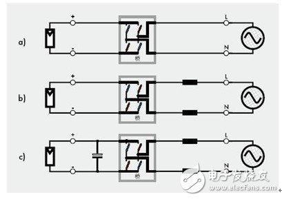
Figure 1: Basic design of a photovoltaic inverter 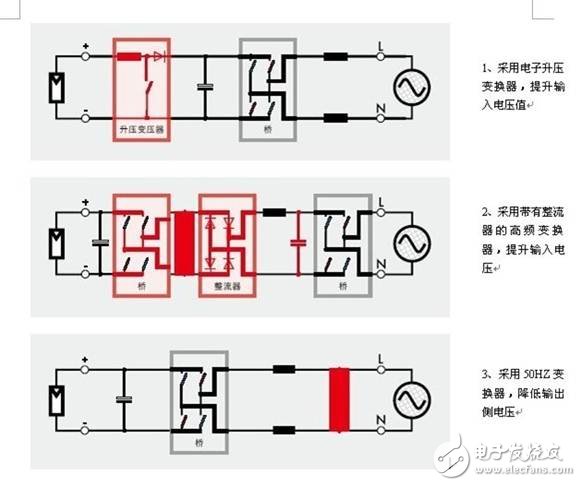
Figure 2: List of the most commonly used inverter circuit diagrams 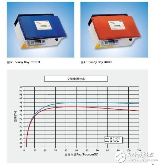
Figure 5: Same appearance, different internal circuits: two types of Sunny Boy efficiency characteristics: transformer type and transformerless type 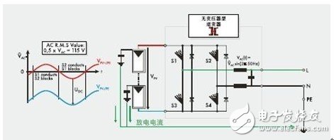
Figure 6: Sunny Boy 2100TL Inverter Photovoltaic Battery Pack Ground Voltage 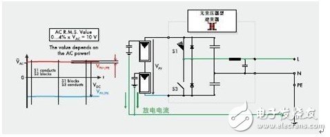
Figure 7: Sunny Boy 5000TL HC Multi-String Inverter Photovoltaic Battery Pack Ground Voltage
Basic design of grid-connected photovoltaic inverter