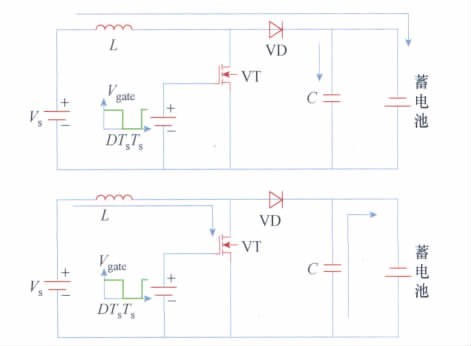
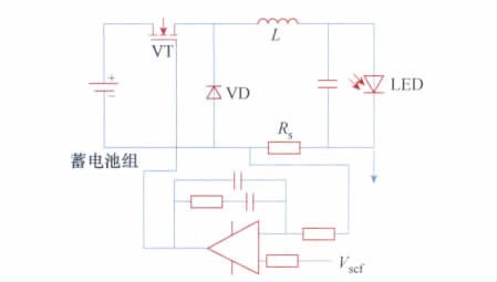
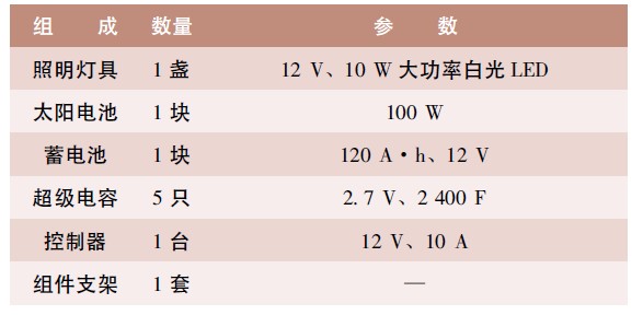
In order to highlight the concept of “energy saving and environmental protection†of intelligent buildings, solar street lights have been designed for smart communities. Designed for lighting fixtures, solar panel tilt and capacity, and battery and supercapacitor capacity. The use of new light source LEDs enhances the lighting effect and extends the life of the lamp. The use of super capacitors improves charging efficiency, increases battery life, and reduces battery waste. The results show that solar, LED and super capacitors are a good combination of optimization. At the same time, the use of supercapacitors is conducive to the development and promotion of such green energy storage components. In today's increasingly serious energy crisis, the development and utilization of solar energy not only saves energy but also protects the environment. Solar street lights do not need to be wired, and are easy to install. After an investment, there is no need for future electricity bills, and the daily maintenance workload is small, so it is very popular and its application is becoming wider and wider. As a smart community with the theme of energy conservation and environmental protection, solar energy should be fully utilized. A smart community in Chenzhou City installed 12 solar street lamps in the sunny fitness square and gate. The design is described below. I. Project Overview Most of the residential buildings are small high-rise buildings. The lighting on the roadside is not enough. It is not suitable for solar streetlights. Therefore, solar street lights are only used in the sunny quarters of the fitness square and the gate. The square is 80 m long and 20 m wide. According to the streetlight specifications of residential quarters, 5 ç› solar street lights were installed on both sides of the square, with a spacing of 20 m. The gates of the community were installed with 2 ç›, a total of 12 solar street lights. Second, the system structure and design The intelligent community is not only a high-tech application, but also pays more attention to energy conservation and environmental protection. The solar street lighting system is further optimized on the basis of general solar street lamps, using LED light sources and super capacitors for higher charging efficiency and longer component life. More energy efficient and environmentally friendly than general solar street lights. The solar street lamp system is mainly composed of photovoltaic cell plates, energy storage batteries, super capacitors, lighting fixtures and controllers. 1. Design of lighting fixtures and control methods (1) Design of lighting fixtures The traditional lighting fixtures have low efficiency, such as incandescent lamps, tungsten halogen lamps, etc., which are not suitable for the energy-saving concept of intelligent buildings. The performance comparison of various illumination sources is shown in Table 1. The white light ultra-high brightness LED luminaire has a luminous efficiency of 45 lm/W. Although it is not high, the emitted light is in the visible range and is suitable for illumination sources. LED lamps have a long life span of more than 100 000 h, which can effectively reduce lamp waste. In addition, the LED is powered by a low-voltage DC power supply, which is safer and suitable for frequent opening and closing. Therefore, the solar lighting system selects 12 V, 10 W white light super bright high-power LED lamps, the luminous efficiency can reach 450 lm / W, equivalent to 50 W incandescent lamps, can achieve good lighting effects. Table 1 Technical performance of common street light source (2) Control method of lighting fixtures There are two main ways to control the opening and closing of solar lighting: timing control and lighting control. The timing control is set by the system automatically after the daily turn-on and turn-off time, but the setting time needs to be constantly adjusted as the season changes. Otherwise, the dark will not light, and the daylight will not turn off the light, resulting in energy waste. . Illumination control is the system to turn on and off the lighting fixture by detecting the illuminance. If the illuminance is lower than 10 lx, the light is turned on. When the illuminance is above 10 lx, the light is turned off. This can meet the needs of users and save energy, which is in line with the concept of intelligent building. Therefore, the lighting control mode is adopted for the lighting and lighting of the system lighting. The working time of the light control mode is related to the local latitude and the solar declination angle of the day, and the light of the sky is enough to illuminate half an hour before sunrise and half an hour before sunset, so that the street light can be turned off, so that the light can be turned on less than 1 hour per day. The intelligent community is located at 116.84° east latitude and 38.31° north latitude. According to the calculation and actual statistics of the literature [1], it can be seen that the light control street lamps in this area have a maximum working time of 12 h during the winter solstice and the shortest working time during the summer solstice. It is 9h. It can be seen that the change of working time of the solar street lamp is not too large, and it can be considered as a balanced load, which has little effect on the inclination of the solar panel. 2. Solar battery (1) Determination of the optimal tilt angle of the solar panel The solar panels are to be mounted towards the equator, usually facing south or slightly west, and should have a certain angle of inclination relative to the ground plane, ie the solar panel inclination. Because the angle of illumination of the sun changes with time, the amount of solar energy received by the solar panels at a fixed dip angle also changes, so the determination of the inclination of the solar panel is critical to the overall system, in the solar street lighting system. In the optimized design, the optimal tilt angle of the solar panel is determined according to the load condition, the local climate condition and the latitude and longitude, so that the annual average amount of sunlight received is the largest. The load of the system is approximately equalized load, and the optimal tilt angle of the solar panel is determined by the internationally popular "yearly balanced winter maximum" photovoltaic system design principle for receiving solar radiation. That is to say, under the premise of ensuring the balance of solar panels in the whole year, the optimal dip angle maximizes the amount of sunshine in winter, so as to increase the power generation of the system in the weaker days of solar radiation, and meet the needs of balanced charging and load of the battery. Based on the meteorological data of the past 10 to 20 years in Chenzhou City, the model of sky scattering radiation anisotropy can be used to calculate the amount of solar radiation received by solar panels at different dip angles, combined with “the annual equilibrium winter maximumâ€. "The theory, you can determine the solar panel tilt angle to take the local latitude of 38 °. Because the solar irradiance received by the panel with small dip angle in summer is large, the solar irradiance received by the panel with large dip angle in winter is large, so it can be increased by 5° to 10° on the basis of the inclination angle of 38°, the effect will be more Good, and it is conducive to the snow falling, reducing maintenance workload. The solar panel tilt angle of this system is 43°. (2) Determination of solar battery capacity The power of the LED is 10 W, which works 12 hours a day. The power of the solar cell is WS, the efficiency is 40%, and the remaining 20%. The daily sunshine working time is 5 h. WS × 5 h × 40% ÷ 120% = 10 W × 12 h Solved WS = 72 W In order to meet the energy storage requirements of the battery, the solar cell power selection is larger, and the system selects a 12 V, 100 W solar battery. 3. Selection of battery pack and super capacitor At present, large-capacity, low-cost energy storage devices are also lead-acid batteries. Although supercapacitors have many advantages, their energy storage is not easy for a solar street lamp system to cope with continuous rainy days. However, supercapacitors can help the battery to work better. Supercapacitors and accumulators form energy storage components, which can improve charging efficiency, extend battery life and improve system power supply reliability. Its structure is shown in Figure 1. Figure 1 Structure of a solar street light system    (1) Selection of battery pack capacity In the solar street light system, the battery is an energy storage device, and its capacity is directly related to the length of the lighting time. The basis for selecting the battery pack is mainly the rated voltage and rated capacity. The formula for calculating the battery capacity is: Where, C is the capacity of the battery pack, the unit is A·h; D is the longest day without electricity, take 6 days; F is the correction factor of the discharge efficiency of the battery pack, usually taken as 1. 05; Q is the daily electricity The amount is in the range of W·h, and the system takes 120 W·h; L is the charging and discharging efficiency of the battery pack, and is usually taken as 0. 9; U is the discharge depth of the battery pack, usually taken as 0.6; Ka is the line loss, usually Take 0. 98; Vt is the system operating voltage, take 12 V. Calculate the battery pack capacity C = 120 A·h according to the formula, and select one of the 120 A·h /12 V single cells. The daily power consumption of the load is 10 W × 12 h = 120 W·h, that is, 10 A·h, and the 120 A·h battery can provide 12 days of power consumption. According to the discharge depth of 0.6, you can use 7 day. In actual use, the solar street lights can be illuminated normally for 7 consecutive rainy days. (2) Choice of super capacitor Supercapacitor is a new type of energy storage component. It is based on the electric double layer and uses EDLC supercapacitor with porous carbon material as the electrode. It has a capacitance of up to several thousand methods, and its performance is different from traditional rechargeable batteries and ordinary Capacitors can be fully charged in a short period of time, while other rechargeable batteries can store a large amount of electrical energy. During discharge, the electrons between the moving conductors (without relying on chemical reactions) are released to supply power to the luminaire. However, at present, the price is too high, and large-capacity power supply is not easy to implement, and can only be used to assist the battery. The output power of the solar cell changes with the weather. This unstable charging current affects the battery life, which inevitably increases the system cost and causes more environmental pollution. Therefore, the system has designed a super capacitor, an intermediate component that can be quickly charged and discharged. Especially when the sunlight is not strong, the control system stores the unstable electric energy output from the solar cell in the supercapacitor, and then charges the battery with a Constant Current after being filled, so that the life of the battery can be improved, and the energy storage of the super capacitor is It can also provide more energy for street lamps on continuous rainy days and increase lighting time. According to the reference [2], the supercapacitors 5 of the single cell 2. 7 V and 2 400 F are connected in series as a capacitor bank with a withstand voltage of 13.5 V and 480 F. The supercapacitor charging time can be calculated by the following formula: Where C is the rated capacity of the capacitor; dv is the operating voltage change of the capacitor; I is the charging current of the capacitor; t is the charging time of the capacitor. According to formula (1), the charging time of the capacitor of 13. 5 V, 480 F is (the charging current is 10 A) It can be seen that the charging time is very short, which is convenient for the system to charge quickly. The discharge time of the super capacitor is determined by the formula: get: If the discharge cutoff voltage is 3.5 V, the discharge time is: It can be seen from the equation (2) that the energy storage of the supercapacitor can reach 1. 6 h, which prolongs the power supply time of the system. 4. Design of solar controller As a small-scale photovoltaic system, the solar street lamp system should have a loss current of less than 1% of the rated working current. The design of the system controller circuit selects low-power components and uses the voltage composed of the integrated operational amplifier. The comparator is used as a control circuit. This circuit is simple and reliable, easy to maintain, low in cost and extremely low in power consumption. It is a well-matched circuit. The key of this kind of circuit is to design a better voltage hysteresis for the charge and discharge characteristics of the battery. At the same time, the selection of components should be reliable, and the charge and discharge state indicating circuit composed of LEDs becomes a practical function. The controller circuit has anti-battery over-discharge and over-charge functions. The control system adds a super capacitor to the photovoltaic controller and the charging controller, which is connected between the DC bus and the ground to stabilize the voltage of the DC bus and buffer the excessive energy provided by the photo cell, and then discharge to the battery. Provided to the load. The photovoltaic controller is usually designed with a booster circuit to generate a higher voltage than the two ends of the photovoltaic panel to facilitate charging the battery, and also overcomes the drawbacks of the anti-backfill diode in the conventional circuit to clamp the battery voltage to 12 V. . However, when the light is insufficient, if the battery is to be continuously charged, the control circuit will cause the working point of the photovoltaic cell to be separated from the maximum power output point, which will cause the power generation efficiency of the photovoltaic street lamp system to decrease. Therefore, when designing the control system, the threshold of the weak light segment needs to be preset to achieve the purpose of ensuring normal charging of the battery through the supercapacitor buffer under low light. If the photovoltaic battery is used to charge the battery directly, when the illumination is weak and there are other interference factors, the output voltage will be unstable, which makes it difficult for the photovoltaic cell to remain at the minimum charging voltage during charging, and finally the system cannot be in the illumination range. The battery is charging normally. The system accumulates the unstable output energy of the solar cell on a cloudy day by using a super capacitor, and when the certain voltage condition is satisfied, the energy in the super capacitor is released to the battery through the boost circuit, and the boost circuit diagram is as shown in FIG. 2 . . This method of using a super capacitor can improve the power generation efficiency when the sunlight is not irradiated. Figure 2 charging boost circuit The control circuit of the LED is relatively simple, DC drive can be used, and its life can reach 100,000 h. However, the magnitude of the drive current greatly affects the life of the LED. If the current is too large, the LED light decay may be severe and the lifetime may be reduced. Therefore, the driver circuit must be designed reasonably. Figure 3 shows the LED constant current control circuit realized by the BUCK circuit. Figure 3 LED constant current control circuit 5. Lightning protection grounding design The LED street lamp has an operating voltage of 12 V and is a safe voltage. It is not grounded. However, the LED street light metal pole should be grounded and the grounding resistance is tested to 8 Ω, which meets the requirements. Configuration of solar street lighting system. The basic system configuration of a solar street light in this intelligent community is shown in Table 2. Table 2 Basic configuration of solar street light system Third, the conclusion After the intelligent community solar street light system is put into operation, the 10 W new LED light source is enough for lighting. The application of super capacitor can ensure reasonable charging of the battery, improve the charging efficiency and prolong the life of the energy storage components, especially the sunlight is not enough. At the time, the system is better able to store energy, and its energy storage can be used continuously for 7 days. The design of the system always follows the concept of “energy saving and environmental protection†of intelligent buildings, applying solar energy, long-life LED light sources and super capacitors. If 25 supercapacitors are added, the capacitor energy storage can supply the street lamp for one day. As the capacity of the supercapacitor expands and the price decreases, it is feasible to use it as an energy storage component. The solar streetlight system of the intelligent community is also An attempt at supercapacitor applications.
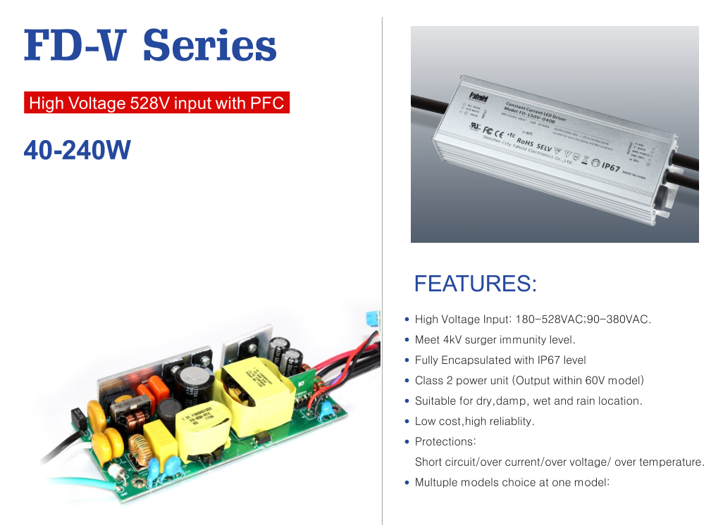
Top features include:
Multiple Options Available for Each Model
200-480Vac High Voltage Input LED Driver High Voltage Input LED Driver,480V industrial High Voltage Driver,LED Driver High-bay Environments Application,IP67 LED Drivers ShenZhen Fahold Electronic Limited , https://www.fahold.com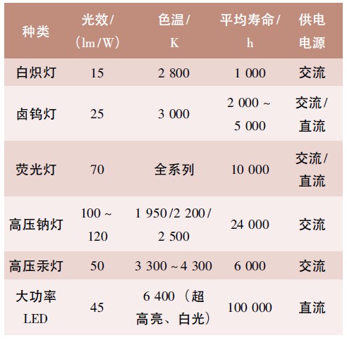


2 times
Window._bd_share_config = { "common": { "bdSnsKey": {}, "bdText": "", "bdMini": "2", "bdMiniList": false, "bdPic": "", "bdStyle": " 0", "bdSize": "24" }, "share": {}, "image": { "viewList": ["qzone", "tsina", "tqq", "renren", "weixin"], "viewText": "Share to:", "viewSize": "16" }, "selectShare": { "bdContainerClass": null, "bdSelectMiniList": ["qzone", "tsina", "tqq", "renren" , "weixin"] } }; with (document) 0[(getElementsByTagName('head')[0] || body).appendChild(createElement('script')).src = 'http://bdimg.share. Baidu.com/static/api/js/share.js?v=89860593.js?cdnversion=' + ~(-new Date() / 36e5)];