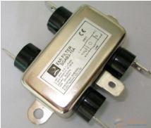
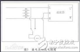
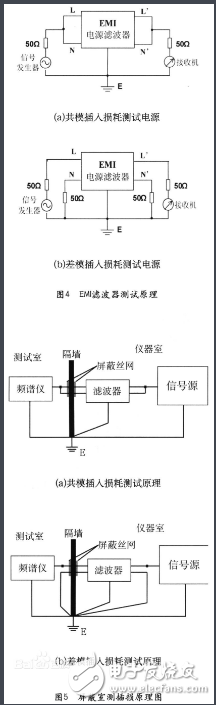
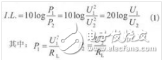
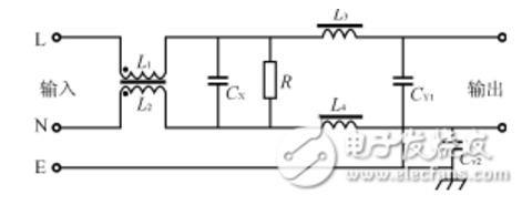
This article mainly introduces the parameters and structure of the power supply filter. I hope this article can give you a deeper understanding of the power supply filter. The power filter is an electrical equipment that effectively filters out the frequency point of a specific frequency in the power line or the frequency other than the frequency point. The function of the power filter is to obtain a power signal of a specific frequency by connecting the power filter to the power line, or to eliminate the power signal of a specific frequency. Using this characteristic of the power supply filter, a square wave group or compound noise after passing the power supply filter can be turned into a sine wave of a specific frequency. High-power power filters such as Satons, UBS, inverters, etc. will generate a large amount of harmonic currents. This type of filter requires active power filter APF. APF can filter out the 2~50th harmonic current. The power filter is a passive two-way network, one end of which is the power source, and the other end is the load. The principle of the power filter is one kind-impedance adaptation network: the greater the impedance adaptation between the input and output sides of the power filter and the power and load sides, the more effective the attenuation of electromagnetic interference. Power filter parameters Leakage current Leakage current refers to the current flowing between the phase line and the neutral line and the filter housing (ground line) under a voltage of 250VAC. It mainly depends on the value of the grounding capacitance (common-mode capacitance). Larger common-mode capacitor CY can increase insertion loss, but it causes larger leakage current. The leakage current test circuit is shown in the figure: Withstand voltage In order to ensure the performance of the power filter and the safety of equipment and personnel, a withstand voltage test must be carried out. The withstand voltage test is a test under extreme working conditions. If the CX capacitor's withstand voltage performance is not good, it may be broken down when there is a peak surge voltage. Although its breakdown does not endanger personal safety, it will make the filter function loss or performance degradation. In addition to meeting the requirements of ground leakage current, CY capacitors also have sufficient safety margins in terms of electrical and mechanical properties to avoid breakdown and short-circuit under extremely harsh environmental conditions. Therefore, the withstand voltage performance between the line and the ground is of great significance to the protection of personal safety. Once the insulation protection measures of the equipment or devices fail, it may cause casualties. Performance evaluation The most important considerations when using EMI power filter are rated voltage and current value, withstand voltage performance, and leakage current. Among them, the most important evaluation performance is the insertion loss performance of the filter. EMI power filter's ability to suppress interference noise uses insertion loss I. L. (Insertion Loss) to measure. Insertion loss is defined as the ratio of the power P1 transmitted from the noise source to the load when there is no filter connected to the power P2 transmitted from the noise source to the load after the filter is connected, expressed in dB (decibel). Frequency domain test 1. Standard test of insertion loss It is stipulated in the standard measurement method that its insertion loss characteristics should be tested in a system with any resistance value between 50Ω and 75Ω. 2 . Insertion loss loading test In EMI filter products, due to the use of inappropriate materials, it is impossible for the common mode choke to guarantee complete symmetry, which will cause the saturation of the magnetic ring. At the same time, the parasitic differential mode inductance may also cause the saturation of the magnetic ring, making the actual use of the filter There is a big gap between the situation and the data provided by the manufacturer, so a load test must be applied to the filter. 3. Time domain test of EMI filter Generally, for EMI power filters, we only care about its conventional performance and frequency domain suppression performance. As for the EMI signal line filter, because the transmission line itself will produce certain electromagnetic interference, the test signal will inevitably produce a certain attenuation. At this time, we have to test its transmission performance in the time domain. Use a 50kHz square wave to filter the filter pin with a capacitance value of 8000pF, and it is found that the rising and falling edges of the time domain have obvious changes. In the frequency domain, after filtering, the high frequency components of the square wave signal are filtered out. For the same filter pin, the higher the frequency of the square wave, the greater the attenuation of its harmonic signal by the filter pin, and the longer the rise and fall time of the square wave. Similarly, for the same frequency waveform, through the filter pin, the greater the filter capacitance value, the greater the slower the rise time of the square wave. 4. EMI filter insertion loss automatic test system design As the content of EMC testing is becoming more and more complex, the test workload has increased sharply, and the requirements for test equipment in terms of function, performance, test speed, and test accuracy are also increasing. In this case, traditional manual testing has been difficult to meet the requirements. Both the National Standard (GB) and the National Military Standard (GJB) require that electromagnetic compatibility testing must be performed automatically, and there are strict requirements for data post-processing. Therefore, the development of EMC automatic testing has become an inevitable way. The automatic test system established in this article uses virtual instrument technology, a system based on the signal source-spectrum analyzer to test the insertion loss of the EMI power filter. The power supply EMI noise filter is a passive low-pass filter, which transmits the AC power to the power supply without attenuation, and greatly attenuates the EMI noise introduced with the AC power; at the same time, it can effectively suppress the EMI noise generated by the power supply equipment and prevent They enter the AC grid and interfere with other electronic devices. Basic structure of power filter It is a four-terminal passive network composed of lumped parameter components. The main components used are common mode inductors L1, L2, differential mode inductors L3, L4, and common mode capacitors CY1, CY2 and differential mode capacitors CX. If this filter network is placed at the input end of the power supply, L1 and CY1 and L2 and CY2 respectively constitute a low-pass filter between two pairs of independent ports on the AC inlet, which can attenuate the common mode interference on the AC inlet Noise prevents them from entering the power supply equipment. The common-mode inductance coil is used to attenuate the common-mode noise on the AC inlet line. L1 and L2 are generally wound with the same number of turns on the ferrite core of the closed magnetic circuit in the same direction. The magnetic flux generated by the alternating current in the two coils cancels each other out, so that the magnetic core does not cause the magnetic flux to saturate, and the inductance value of the two coils is larger in the common mode state and remains unchanged. Differential mode inductance coils L3, L4 and differential mode capacitor CX form a low-pass filter between the independent ports of the AC incoming line to suppress the differential mode interference noise on the AC incoming line and prevent the power supply equipment from being interfered by it. The power filter shown in the figure above is a passive network, which has two-way suppression performance. Inserting it between the AC power grid and the power supply is equivalent to adding a blocking barrier between the EMI noise of the two. Such a simple passive filter plays a role of two-way noise suppression, which can be used in various electronic equipment It has been widely used. Power filters are generally designed as passive filters consisting of resistors, capacitors, and inductors, without active components such as transistors. The picture on the right is an example of a power supply filter. The top of the power supply filter is connected to the power supply. There is a common mode inductor at the power supply end, that is, the two wires of the power supply are wound on the core in the same direction. If there is a common mode signal on the power supply line, The magnetic fields generated by the common mode inductors will add up, so there is a larger impedance, and the magnetic fields generated by the common mode inductors for the differential mode signals will cancel each other, so the common mode inductors can flow. The current flowing through the power supply is mainly in the differential mode, but the noise may also appear in the form of differential mode. To suppress the differential mode noise, you need to use a differential mode inductor or have a separate inductor for each phase. Special safety decoupling capacitors are used on the power filter, which are divided into two types: X capacitors and Y capacitors: X capacitor: suppress differential mode interference (interference between power lines). Y capacitor: Suppress common mode interference (interference between each group of power lines and the ground). Since the increase in Y capacitance will increase the leakage current of the electrical appliance, and the leakage current of the electrical appliance has its specified range, the Y capacitance cannot be too large, and it will generally be smaller than the X capacitance. X capacitor and Y capacitor are safety capacitors, that is, they will not cause electric shock after failure, and will not affect personal safety. Both have a self-healing effect, which will restore the original insulation state of the partially short-circuited part. This is the end of the relevant introduction about the power supply filter. Do you understand the parameters and structure of the power supply filter now? I hope this article will give you a deeper understanding of the power supply filter. If you have any deficiencies, please correct me. M5 Circular Connectors,M5 Waterproof Circular Connector,M5 Waterproof 4P Male Connector,M5 Male Head Waterproof Connector Shenzhen HuaTao Electronic Co., LTD , https://www.htconnector.com