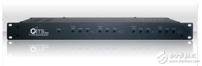
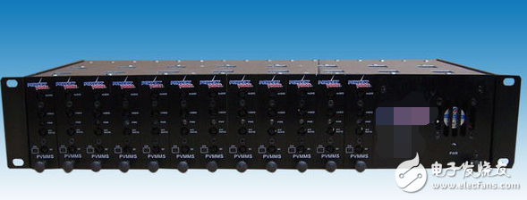
The adjacent frequency modulator (also known as the RF modulator, FM modulator or TV modulator) is one of the main devices in the front-end cable TV room. Its function is to modulate the video signal (VIDEO) and audio signal (AUDIO) provided by the signal source (which can be an AV TV set-top box, a satellite digital TV receiver, a DVD player, a computer, a video camera, a TV demodulator, etc.). A stable high frequency RF oscillation signal. The video is an amplitude modulation method, and the audio is an FM modulation method. According to the different color TV systems in the world, the adjacent frequency modulator also has three modes: PAL modulator, NTSC modulator, and SECAM modulator. The PAL-D system is adopted in China. 1. The TV modulator's video/audio input port is added to the standard video and audio test signals, the field strength meter is connected to the output port, and the standard demodulator is connected to the output side. 2. Adjust the output image and then spell the code switch so that the output carrier frequency is the required frequency. 3. Adjust the input video signal amplitude knob to make the video modulation degree 87.5%. 4. Use the field strength meter to measure the image carrier level, accompany the sound carrier, and adjust the sound carrier level so that the A/V ratio is equal to the design requirement. 5. Adjust the output level attenuation knob so that the output level is equal to the operating level. 1. The adjacent frequency modulator adopts the fixed channel output of the PAL-D system adjacent frequency modulation mode in the 48MHz-750MHz frequency band. 2. In the circuit design, the idea of ​​image frequency and audio frequency CPU double phase-locked loop (PLL) design is adopted. 3. Imported high-quality broadcast-grade modulation chips (TOSHIBA, MOTOROAL, INTECH, TEXASINSTRUMENTS, FAIRCHILD, etc.) are used on the devices. 4, using high performance surface acoustic wave (SAW) filtering, vestigial sideband suppression greater than 65dB. 5, 110dBuv RF output, stable amplitude and accurate frequency. 6, unique filtering method, out-of-band output suppression is greater than 65dB. 7, image modulation, audio frequency offset, A / V ratio, RF output level can be adjusted. 8, 19-inch standard chassis design, standardized installation. Ic Interface Analog Switches,Interface Direct Digital Synthesis,Interface Drivers Receivers Transceivers,Ic Chip Integrated Circuit Shenzhen Kaixuanye Technology Co., Ltd. , https://www.iconlinekxys.com