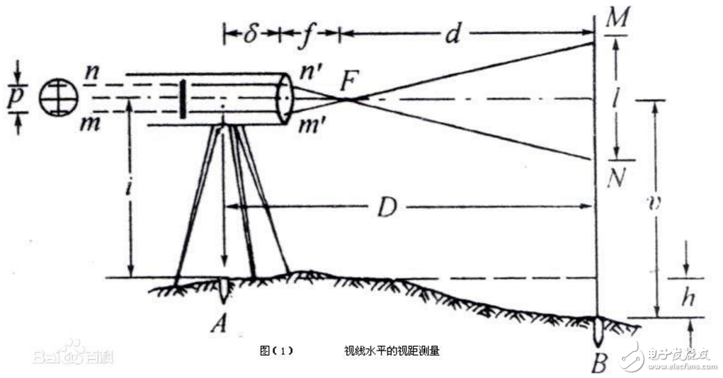
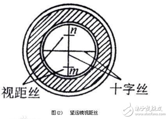
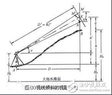
The line-of-sight measurement is to use the thesis line on the crosshair reticle on the telescope and the level gauge to read on the line of sight (level gauge). According to the optical and geometric principles, the horizontal distance and height of the instrument to the ground point are simultaneously measured. A method of difference. Line-of-sight measurement has the advantages of simple operation, high speed, and no influence on ground fluctuations, and is widely used in the measurement of broken parts. However, its ranging accuracy is low, about: 1/200-1/300. Thumb distance measurement (trigonometric function and dense position) Stretch the arm forward and raise the thumb, close the left eye, form a straight line with the right eye, thumb, and target, close the right eye, open the left eye, and remember the left eye at this time. Extend the thumb to the right side of the straight target, visually measure the distance from that point and multiply by 10, which is the approximate distance you get to the target. The "thumb distance measurement method" is a hypothetical distance measured according to a right-angle trigonometric function. We have a target at N meters and measure our distance to the target: 1. Level up our right arm, right hand fist and set thumbs up 2. Use the right eye (left eye closed) to overlap the left side of the thumb with the target in a straight line; 3, the right arm and thumb do not move, close the right eye, and then use the left eye to observe the left side of the thumb, you will find this edge away from the right side of the target a distance; 4. Estimate this distance (this can also be measured), and this distance &TImes;10, the number is our approximate distance from the target. Since each person's arm length and the pupil spacing of the two eyes are different, the distance measurement method needs to be strictly different from person to person, and the ordinary person who has undergone ordinary training can achieve a positive and negative error of 5 meters within 200 meters. Line-of-sight measurement is a method of simultaneously measuring the distance and height difference by using the line-of-sight device in the telescope and the line of sight according to the principle of geometric optics and triangulation. Features: This method has the advantages of convenient operation, high speed, and is not limited by the height fluctuation of the ground. As shown in Figure (1), to determine the horizontal distance D and the height difference h between the two points A and B, the theodolite can be placed at point A, the vertical point of the point B, the line of sight of the telescope, and the line of sight of the point B. At this time, the line of sight is perpendicular to the line of sight. If the M and N points are imaged on the two line-of-sight lines m, n on the cross-hair reticle, the length of the MN on the ruler can be obtained from the difference between the upper and lower line-of-sight silk readings. The difference between the upper and lower wire readings is called the line of sight interval or the ruler interval. In Figure (1), l is the line of sight interval, p is the pitch of the upper and lower line of sight, f is the focal length of the objective lens, and δ is the distance from the objective lens to the center of the instrument. From the similar triangle m'n'F and MNF can be obtained: d: f = l: p, that is: d = fl / p, as seen from the figure D = d + f + δ, brought in: D = fl / p +f+δ, let f/p=K,f+δ=C, get D=Kl+C.(1) In the formula, K, C - line of sight multiplication constant and line of sight plus constant. The line of sight constant of the modern internal light telescope is designed to have K=100 and C close to zero. Then formula (1) can be reduced to D = Kl = 100 & TImes; l. (2) And the height difference h=iv, (3) i—The instrument is high, which is the height from the top of the pile to the center of the horizontal axis of the instrument; v—the aiming height is the reading of the wire in the crosshair on the ruler. When performing line-of-sight measurement in an area where the ground is undulating, the line of sight must be tilted to read the line-of-sight interval, as shown in Figure (3). Since the line of sight is not perpendicular to the line of sight, the above formula cannot be directly applied. If the line-of-sight interval MN can be converted into a line-of-sight interval M'N' perpendicular to the line of sight, the line of sight can be calculated according to formula (2), that is, the figure (3) slant range D', and then according to D' and vertical The right angle α calculates the horizontal distance D and the height difference h. So the key to solving this problem is to find the relationship between MN and M'N'. In the figure, the angle φ is very small, about 34', so the angle MM'E and the angle NN'E can be approximated as a right angle. It is easy to calculate l'=M'N'=MNcosα=lcosα, then D'=Klcosα . (4) It is easy to find the horizontal distance D=Klcosα*cosα, (5) The height difference h=D*tanα+iv. (6) In fact, α is 0°, sin0°=0, cos0°=1, and (2), (3) can be obtained by taking (4), (5), and (6). The line of sight is equal to the horizontal distance when the line of sight is horizontal. When measuring, as shown in Figure (3), place the instrument at point A, measure the height i of the instrument, and turn the sighting part to aim at the point B of the point of view. Read the readings of the upper, lower and middle wires respectively. , V, calculate the line of sight interval l = MN. Then the vertical index level tube bubble is centered (if the theodolite for the vertical index automatic compensation device does not have this operation), the vertical reading is read, and the vertical angle α is calculated. Then use the calculator to calculate the line of sight, horizontal distance and height difference according to formulas (4), (5), and (6). Toolkits For Cutting Mahine and Cutting Materials
It is suitable for the blade of the Screen Protector Cutting Machine and the tools for installing the Screen Protection Film.
If you want to learn more about Accesseries For Cutter,Screen Protector Cleaning Tool, Cutting Blade, Cell Phone Scraper Tool, Tool Kit, Cutting Head Parts please click "Product Details" to view Accesseries For Cutter,Screen Protector Cleaning Tool, Cutting Blade, Cell Phone Scraper Tool, Tool Kit, Cutting Head Parts parameters, models, pictures, prices and other information .
Accesseries For Cutter,Screen Protector Cleaning Tool, Cutting Blade, Cell Phone Scraper Tool, Tool Kit, Cutting Head Parts Shenzhen Jianjiantong Technology Co., Ltd. , https://www.jjttpucuttingplotter.com