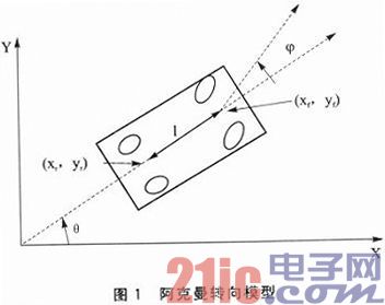
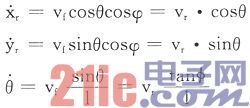
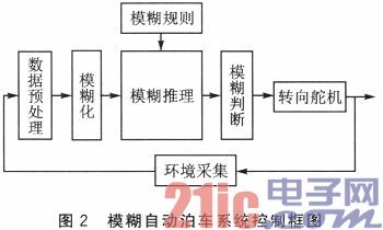
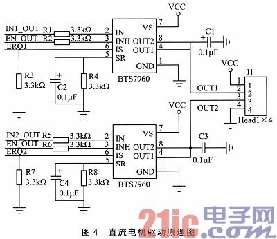
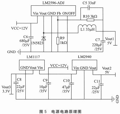
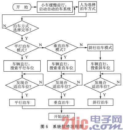
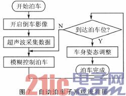
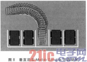
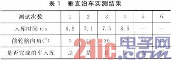
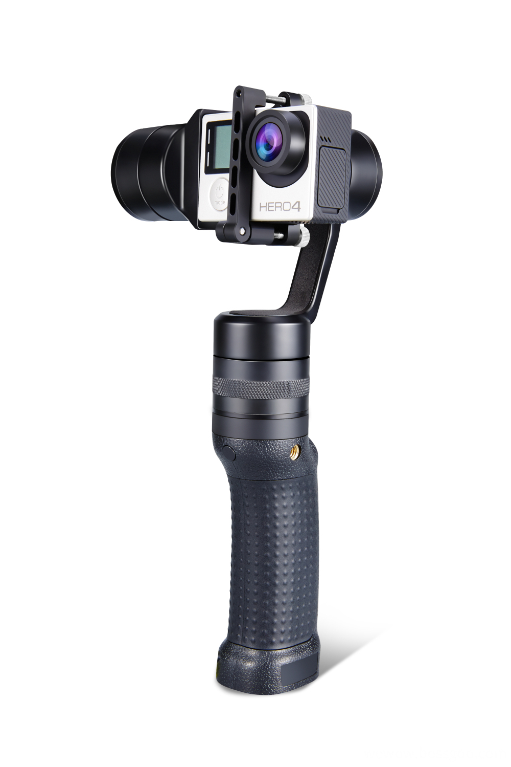
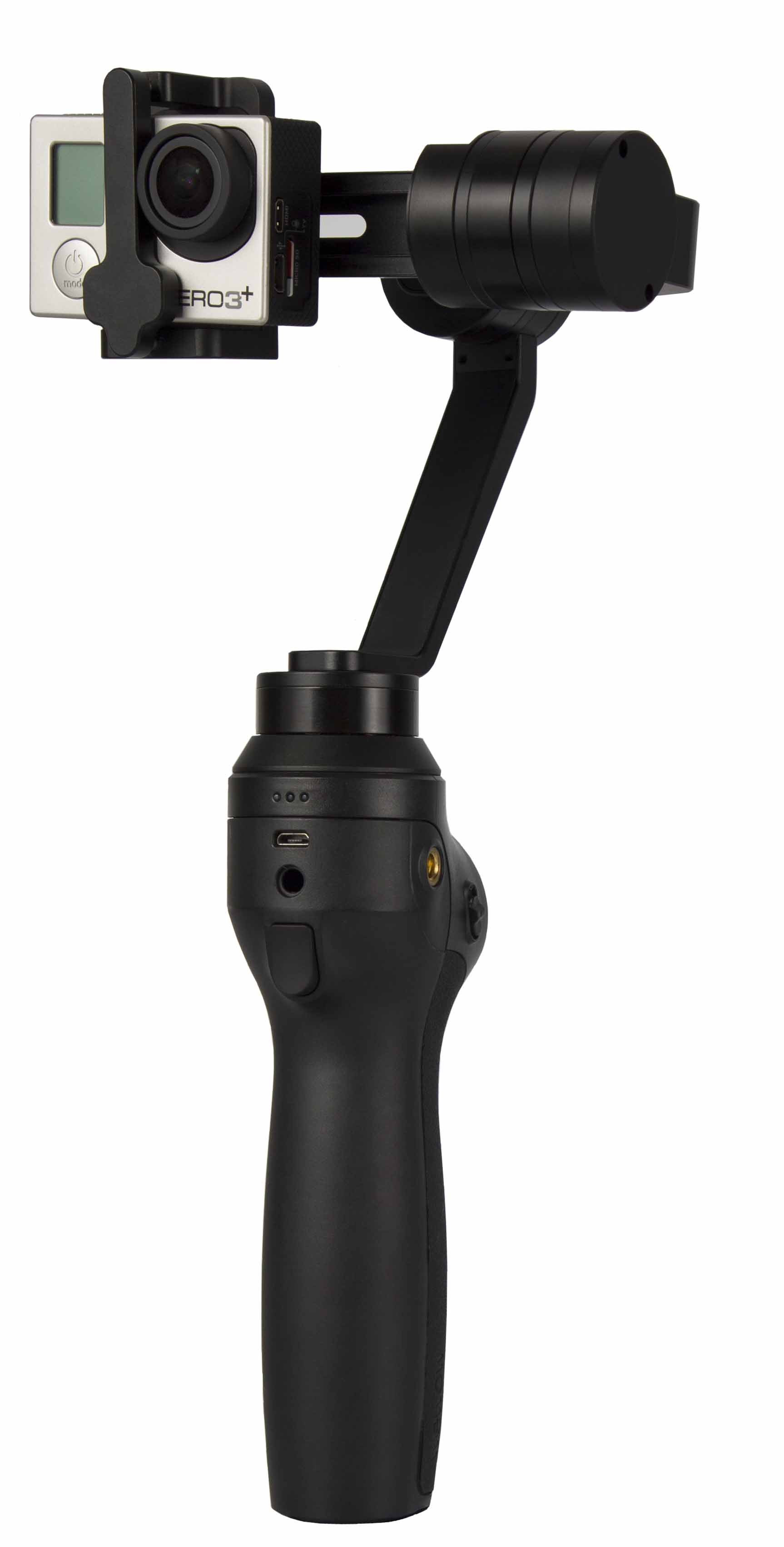
Abstract: An automatic parking system model based on ultrasonic ranging is designed. Firstly, the car motion model is analyzed, and the three parking fuzzy controllers are vertically, parallelly and obliquely designed in real time, and the simulation is verified in Simulink of Matlab. Ultrasonic ranging technology, video acquisition technology, etc. are used to obtain the surrounding environment data. According to the actual vehicle and garage size, the car model and the garage model are designed by scaling, and the fuzzy controller passed through the verification is converted into C code and embedded into Automated parking feasibility test in the Freescale K60 main control panel. After testing, when the heading angle of the model car is in the range of -32° to +32°, the autonomous parking of the model car in the 0.92 times standard size model garage is realized. This article refers to the address: http:// introduction In recent years, with the development of the economy, there are more and more families with cars. For the inexperienced drivers, the problem of safe parking in crowded parking lots, garages and roadsides is becoming more and more prominent. The emergence of an automatic parking system increases the accuracy of the parking process. Compared with the foreign independent research and development of the independent parking system, the current research on the automatic parking system in China is still in its infancy, and only a few high-end cars are equipped with an automatic parking assistance system. Designing the parking system model to verify the parking control algorithm can provide a theoretical basis for the real vehicle development of the automatic parking system, and promote the automatic parking system to replace the driver to observe and judge, to achieve automatic parking in place, thereby reducing parking accidents happened. 1 Principles and algorithms 1.1 Ultrasonic ranging principle Ultrasonic waves are sound waves with a frequency higher than 20 000 Hz. They are highly directional and travel far in the medium, so ultrasonic waves are often used for distance measurement. Ultrasonic testing is often quick, convenient, simple to calculate, and easy to control in real time. Ultrasonic transmitting device transmits ultrasonic waves in a certain direction. When the ultrasonic wave is emitted, the timer is turned on. The ultrasonic wave propagates in the air, and immediately returns to the obstacle when it hits the obstacle. The ultrasonic receiver stops timing immediately after receiving the reflected wave. Using the velocity v of the ultrasonic wave propagating in the air and the time t recorded by the timer, using the formula s=v×t/2 It is possible to calculate the distance s of the emission point from the obstacle. The system requires high measurement accuracy. Since the speed of ultrasonic propagation is greatly affected by temperature changes, the temperature is corrected by temperature compensation. It is obtained by the following formula: Where: τ is Celsius. The system uses 8 ultrasonic devices to be placed around the model car to form an environmental measurement device, which can accurately locate the parking space in the environment and obtain the attitude angle of the vehicle from the surrounding environment to ensure the reliability of the system. 1.2 Modeling of motion models In order to solve the special driving process of automatic parking more intuitively and simply, the vehicle kinematics model is established for the model car, that is, the car is simplified into a rectangular rigid body, and the kinematics model of the car based on Ackerman steering geometry is established. For the car model studied in this paper, it can be simplified into a two-wheeler model, and the vehicle's motion is described with reference to the midpoint of the front and rear axles of the vehicle. The established Ackerman steering model is shown in Fig. 1. In the figure, (xf, yf), (xr, yr) represent the coordinates of the midpoint of the front and rear axles of the vehicle; φ represents the front wheel angle; θ represents the heading angle of the vehicle; l represents the wheelbase of the vehicle; vr represents the center point speed of the rear axle, The simplified vehicle kinematics equations are: It is analyzed by the above kinematics equations: under low speed motion, the trajectory of the center point of the rear axle of the model car is a fixed circle, and the radius of the circle is only related to the front wheel angle φ of the vehicle. According to the actual vehicle size, the car model and parking environment are designed proportionally, and the Ackerman steering model is established in Matlab/Simulink, which provides a good theoretical basis for the following fuzzy controller design. 1.3 Automatic parking fuzzy controller design Fuzzy control is a kind of computer control method based on fuzzy linguistic variables, fuzzy set theory and fuzzy reasoning. It is suitable for complex systems with mathematical models. Fuzzy control inherits the natural language habits of human conceptual models and thinking images. Compared with other traditional control methods, fuzzy control is more widely used in automatic parking systems. The design of automatic parking fuzzy controller includes vertical parking fuzzy controller design, parallel parking fuzzy controller design and oblique parking fuzzy controller design. Since the three controllers are designed in a similar way, this paper discusses vertical parking as an example. Fuzzy controller design. The control block diagram of the fuzzy automatic parking system of this design is shown in Figure 2. Among them, fuzzy, fuzzy reasoning, fuzzy judgment and fuzzy rules constitute the fuzzy controller. The CPU mainly implements fuzzy control through the following three steps: 1 First, the coordinates of the rear center axis of the vehicle (Xr, yr) and the heading angle θ of the vehicle body are obtained by the ultrasonic array, and the data sampled by the ultrasonic sensor is blurred. 2 According to the fuzzy control rules, combined with the actual parking experience of the driver, the fuzzy control amount is calculated. 3 The fuzzy control quantity is judged, and the exact output is obtained to the steering servo to control the front wheel steering of the model vehicle. Through the simulation analysis of the above fuzzy controller, the adjustment is appropriately performed in the actual operation, and the precise parking control is finally realized by repeated debugging. 2 hardware design and simulation The design hardware circuit mainly includes Freescale K60 minimum system module design, ultrasonic circuit design, steering motor drive circuit design, DC motor drive circuit design, and voice module circuit design. The hardware system circuit block diagram is shown in Figure 3. When the vehicle passes the parking position, the signal of the ultrasonic sensor is received by the controller, thereby identifying and storing the scale information of the parking space, and establishing a map of the parking area. The parking system is started, the core controller controls the steering gear drive circuit to drive the steering servo, and the steering angle of the steering gear is fed back to the core controller by the dual-axis gyroscope to form a PID closed-loop control, and an accurate front wheel rotation control amount φ is obtained. The DC motor drive circuit drives the DC motor. The encoder obtains the current speed feedback to the core controller and drives the second PID closed-loop control to make the vehicle speed stable and the system more stable. During the parking process, the reversing image obtained by the camera is stored in the internal DMA controller of the core controller K60 and finally displayed on the display. When the appropriate parking space is found and the parking is over, the voice module is controlled to make a voice reminder to make the system more intelligent. 2.1 DC motor drive circuit The DC motor drive circuit is mainly used to control the rotation direction and rotation speed of the DC motor. The automatic parking system can be controlled to start the parking operation by changing the voltage across the DC motor. The surrounding environment information is sensed by the ultrasonic wave, and the parking is realized by the fuzzy control. FIG. 7 is a flow chart of the automatic parking subsystem. The steering of the motor is controlled; while the speed of the DC motor is controlled, there are different solutions. The conventional method uses PWM control. The drive circuit directly selects the full H-bridge drive module composed of Infineon's high-power drive chip BTS7960. The BTS7960 includes a current detection circuit, a control drive circuit, and a P-type and an N-type MOSFET. It can be flexibly applied to the control drive circuit of 2-phase or 3-phase, DC brushed or brushless motors, which not only simplifies Circuit design and make control easier. The motor drive schematic is shown in Figure 4. 2.2 Power circuit The stability of the power supply circuit plays a decisive role in the stability of the system. The power supply circuit provides different levels of voltage for different module circuits. This model car design requires three levels of voltages of 3.3V, 5V, and 12V. The power supply is supplied by a 12 V lithium-ion battery. The schematic diagram of the power supply circuit is shown in Figure 5. The system uses the LM1117 chip to step down the voltage from 12 V to 3.3 V to power the Freescale microcontroller; the series regulator chip LM2940 is regulated and outputs 5 V to supply power to the CMOS camera, ultrasonic module and LCD display. The servo drive is regulated to 5 V by the adjustable voltage regulator LM2596-ADJ, and the steering gear drive module is connected to drive the steering gear steering servo. 3 system software design The automatic parking system model, after starting the automatic parking system, selects three types of parking modes: vertical, parallel and oblique. Ultrasonic ranging results in the vehicle's rear axle center coordinates (xr, yr) and front wheel angle φ and the body heading angle θ. The input fuzzy controller controls the reverse running state of the vehicle to realize automatic parking. The system software flow chart is shown in Figure 6. The automatic parking system starts the parking operation, and the surrounding environment information is sensed by the ultrasonic wave, and the parking is realized by the fuzzy control. FIG. 7 is a flow chart of the automatic parking subsystem. 4 Testing and analysis In this design, a fuzzy control parking system model based on ultrasonic ranging is established. The coordinates of the rear wheel axle center point of the vehicle model are measured by ultrasonic wave as the starting position of the parking. The vehicle kinematics model and fuzzy controller are established in Matlab Simulink, and the automatic parking is established. The vehicle process was simulated to verify the rationality of the fuzzy controller design and the accuracy of the design. The simulation results of Matlab Simulink are shown in Figure 8. On the basis of software simulation, the hardware circuit design is carried out. At the same time, two equally-sized model cars are used as reference vehicles. The empty car parking spaces are reserved according to the actual garage ratio between the two cartons. The actual model car test is carried out by setting up the model. The test results are as follows. Table 1 is listed. It can be seen from the test results that the heading angle of the model car is controlled within the range of 0 to 32°, and the trolley model can realize fast and automatic parking, with high parking accuracy and good system stability. When the heading angle is greater than 32°, the ultrasonic sensor loses certain accuracy due to the tilt of the vehicle body, which causes the model car to misjudge the parking space and its position, which ultimately leads to parking failure. The same situation occurs when parallel and skewed parking tests are performed. The ultrasonic module is tested for distance at different angles. From the test results, when the heading angle is greater than 32°, the error caused by ultrasonic ranging causes the parking system to misjudge the parking space. Conclusion The designed automatic parking system not only can complete the model car automatically find the minimum empty parking space, adopts the fuzzy control method to realize the parking of three parking spaces, and uses the voice module to realize the voice reminder, and displays the road condition behind the reverse on the vehicle display screen. Information makes the design of the laboratory parking system model more humane and intelligent. Three-axis Motion Camera Stabilizer is composed of pan axis, rolling axis and tilt-axis. With a gyro-stabilized gimbal system, it keeps stabilized or steerable horizon with automatic calibration to give you an unprecedented smooth shooting experience.
5. After-sales service, solve within 3 working dates.
Three-Axis Motion Camera Stabilizer Three-Axis Motion Camera Stabilizer,Three-Axis Action Camera Stabilizer,3 Axisl Action Camera Stabilizer,3 Axis Gimbal For Action Camera GUANGZHOU WEWOW ELECTRONIC CO., LTD. , https://www.stabilizers.pl![]()

Our service
1. Reply to you within 24 hours.
2. Already sample: within 1-2days.
3. Shipping date: within 24 hours once get the payment.
4. 12 months warranty.
Wewow appreciates domestic and international business relationship!