Harmonic distortion often occurs when the amplifier works. Through spectrum analysis, it is found that the low-order harmonics of most amplifiers are stronger, and the second-order harmonics are the main ones, and the lower-order harmonics of each order are weakened. The higher harmonics are small, full and bright to hear, full of vitality, good sense of transparency, pure sound, which is a beneficial side. However, if we make improper adjustments or use poor quality components when making a tube amplifier, some other distortions that are incompatible with the Hi-Fi concept will also occur. So how to "strengthen the advantages and avoid the shortcomings, and create quality products"?
1. Non-linear distortion
Non-linear distortion is mainly caused by the tube working at the curved part of the characteristic curve. There are two other situations. One is that the operating point is selected improperly (high or low), and the other is that the signal voltage is too large.
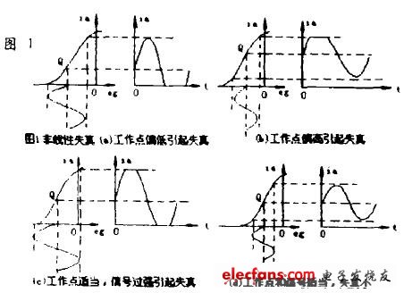
As shown in Figure 1: Non-linear distortion (a) The grid negative pressure is too large, and the operating point (Q) is too low, so that the tube works to the lower curved part of the dynamic characteristic curve. As a result, the negative half cycle of the anode current becomes flat and produces significant Distortion. Figure 1 (b) The negative pressure of the grid is too small, so that the tube works to the upper curved part of the dynamic characteristic curve. As a result, the positive half cycle of the anode current becomes flat and produces distortion. Although the negative voltage of the gate is selected correctly in Fig. 1 (c), the signal voltage is too strong, so the anode current has a flattened positive half cycle and a negative half cycle, and distortion also occurs. Figure 1 (d) The gate negative pressure and signal amplitude are selected appropriately, so the distortion is very small.

Figure 1 Non-linear distortion waveform
It can be seen from the above: when the amplifier has nonlinear distortion, if the input is a sine wave, then the amplified signal becomes a non-sinusoidal wave, and the non-sinusoidal wave can be decomposed into DC, fundamental, and higher harmonic components. So the characteristic of nonlinear distortion is that a new frequency component appears at the output of the amplifier.
The experiment proves that as long as the nonlinear distortion coefficient of the low-frequency amplifier does not exceed a certain range, the human ear is not easy to detect, under normal circumstances. The nonlinear distortion factor of the amplifier should not exceed 10%, and the maximum should not exceed 15%.
Based on the above analysis, we can be sure that nonlinear distortion is harmful to the sound quality. It has been proved through practice that this distortion makes the amplifier deteriorate the sound quality, hoarse, and the language is ambiguous when the amplifier is amplifying the language. In order to reduce the nonlinear distortion, it is necessary to correctly select the operating point (Q) and the signal voltage, so that the amplifier works in the linear part of the dynamic characteristic curve of the tube, that is, in the class A industrial state (this point is especially for beginners) It is very important), and Class B and Class A and B will produce large nonlinear distortion, which must be reduced by using a push-pull circuit before they can be applied.
2. Frequency distortion
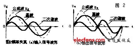
In many cases, the signal to be amplified by the amplifier is not a pure sine wave. For example, language is composed of many sine waves with different frequencies superimposed on a certain proportion. To make the amplified waveform the same as the input waveform, it requires The amplifier has the same amplification factor for all frequency components. If the amplification factor is different for different frequency components, the original proportional relationship between the frequency components will change, thus making the output waveform inconsistent with the input waveform. As shown in Figure 2: Frequency distortion (a) indicates that the gate input signal contains the fundamental wave and the second harmonic, and Figure 2 (b) indicates the amplified output signal, which also has the fundamental wave and the second harmonic. However, because the amplification factor of the second harmonic of the amplifier exceeds that of the fundamental wave, the amplified synthesized waveform is distorted and frequency distortion occurs.

Figure 2 Frequency distortion waveform
We often use the frequency characteristic curve to represent the frequency distortion of the amplifier. The so-called frequency characteristic curve is the relationship curve between the amplification factor K of the amplifier and the frequency f. An ideal amplifier without frequency distortion, the frequency characteristic curve is a straight line parallel to the horizontal axis, as shown by the dashed line in Figure 3. The actual frequency characteristic curve of the Hi-Fi amplifier is shown as the solid line in FIG. 3. This curve shows that within the (fn-fm) audio frequency range, the magnification is uniform, and the frequency distortion generated by the amplifier is very small. However, the frequency characteristics of the transformer-coupled voltage amplifier are not a flat straight line, as shown in the solid part of Figure 4. As the frequency decreases, the inductive reactance of the transformer primary coil decreases. As the voltage across the primary coil of the transformer and the voltage of the secondary coil decrease, the amplification factor of the amplifier decreases. As the frequency increases, at a certain frequency, Co (equivalent capacitance, which includes not only the input capacitance of the lower tube and the distributed capacitance of the wiring, but also the distributed capacitance of the secondary coil) and the leakage inductance can produce series resonance, Therefore, the output voltage increases, the magnification increases, and a peak appears. As the frequency increases again, the impedance exhibited by Co is very small, and the amount of amplification quickly decreases.

Because the actual load of the amplifier is not pure resistance, but contains inductive components. Therefore, the actual load impedance ZL will increase and decrease with the increase and decrease of the signal frequency, so that the anode load impedance Za also increases and decreases with the increase and decrease of the signal frequency. This will cause two undesirable phenomena:
(1) Increased frequency distortion;
(2) The nonlinear distortion increases (because the anode load impedance is not equal to the optimal load impedance required by the electron tube).
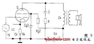
When the amplifier has severe frequency distortion, the amplified language will be blurred. If the low frequency part of the language cannot be amplified well, the sound will become sharp and harsh, and it will be very unpleasant to listen to. In order to overcome the above shortcomings, an RC circuit is usually connected in parallel to the primary side of the output transformer, as shown in Figure 5, so that the total load impedance of the amplifier does not change with frequency as much as possible.

Figure 5 Amplifier should have more serious frequency distortion
The common values ​​of RC are:
C = 0.001 uF ~ 0.01uF
R = (1.5 ~ 2) Za is the best
Sometimes at the primary side of the output transformer, only one (0.001uF ~ 0.005uF) capacitor is added, which can also play a role in compensating the increase of load impedance at high frequency.
In the resistance-capacitance coupling amplifier circuit; generally use high-quality large-capacity (3.3uF ~ 10uF) copper film or silver film super capacitors (such as the Danish JENSEN capacitor) as coupling capacitors to enhance the driving ability of low-frequency signals to The frequency characteristic curve tends to be a straight line, ensuring Hi-Fi amplification.
3. Phase distortion
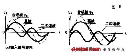
Due to the presence of reactive elements in the amplifier, the phase relationship between the frequency components in the non-sinusoidal signal changes, making the output waveform inconsistent with the input waveform, which is phase distortion, as shown in Figure 6.

Figure 6 Phase distortion waveform
Figure 6 phase distortion (a) is the input signal waveform, Figure 6 (b) is the output signal waveform. During input, the fundamental and second harmonic phases of the signal start from zero, but the phase relationship changes during output, and the second harmonic produces a phase shift, so the synthesized waveform is different from the original, which results in Phase distortion. Solution: It is basically the same as the solution of frequency distortion.
The above analyzes the nonlinear distortion, frequency distortion and phase distortion. One of their common points is that the output waveform generates distortion. The essential difference between them is:
(1) The causes of distortion are different. Frequency distortion and phase distortion are caused by the presence of reactive components (inductors, capacitors) in the circuit, while nonlinear distortion is caused by non-linear components (tubes, core transformers, etc.) in the circuit.
(2) The frequency components in the output signal of the amplifier are different. Frequency distortion and phase distortion can only change the relationship between the amplitude and phase of each frequency component in the signal, while the frequency component of the output signal is the same as the input signal without change. Non-linear distortion requires new frequency components in the output signal.
After recognizing the difference between them, we can reduce or eliminate the distortion according to the characteristics and causes of various distortions.
In fact, three kinds of distortion may appear in the same amplifier. Which kind of distortion has the greatest impact on the operation of the amplifier must be analyzed in detail. For example, when the speech signal is amplified, the human ear has no obvious sense of phase distortion, which is nonlinear Distortion and frequency distortion, the human ear also feels different, the human ear is more sensitive to nonlinear distortion. Therefore, in audio amplifiers, special attention should be paid to reducing nonlinear distortion, followed by reducing frequency distortion, and phase distortion generally does not need to pay attention to it.
Din-Rail Power Supply 12Vdc
12v din rail power supply have 36W and 60W, output current 3A and 5A.
Features:
Wide input range: 100-240V, 50/60Hz.
Easy for the installation and can move in the rail follow CCTV when working
Cooling by free air convection
LED indicator for power on
Protection: short circuit, over current, overload, over voltage.
Efficiency 85%
100% full load burn-in test
3 years warranty
Product application:
Suitable for home automation, CCTV, security camera and led lighting
Din-rail Power Supply 12VDC
Din-Rail Power Supply,Din-Rail Power Supply 12Vdc,Din Rail Power Supply Applications,Din Rail Power Supply 48Vdc
Guangdong Steady Technology Co.LTD , https://www.steadysmps.com