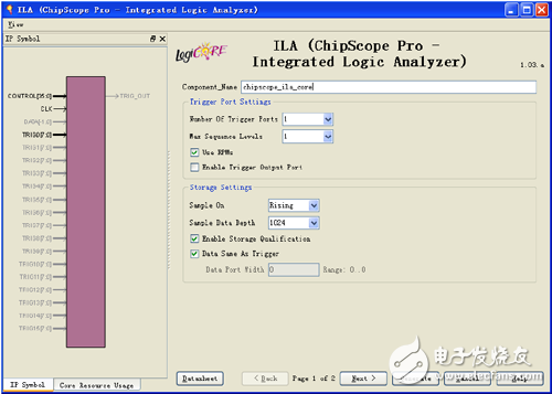
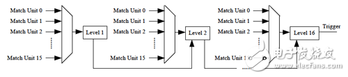
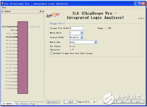
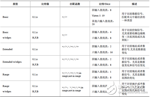
Double-click [Xilinx Core Generator] to open an existing IP core project or create a new IP core project. [View by funcTIon] → [Debug & VerificaTIon] → [ChipScope Pro], double-click ILA. The ILA triggering and configuration interface is displayed, as shown in Figure 9-7. (2) Trigger Port SetTIngs option group: Trigger port settings. [Number Of Trigger Ports]: Set the number of trigger ports. Each ILA core can support up to 16 trigger ports. After setting the number of trigger ports, each trigger port corresponds to a set of options, including trigger width, trigger condition, etc., and the corresponding label is TRIGn, where n represents the trigger port number 0 to 15. [Max Sequence Levels]: Set the maximum sequence level for the trigger condition. As shown in Figure 9-8, the output of the previous stage can be used as the condition of the next level if the condition is satisfied, and so on, and 16 states can be transmitted at the maximum. Figure 9-7 ILA configuration interface Figure 9-8 Block diagram of the trigger sequencer [Use RPMs]: Select whether to generate ILA cores with related layout macros (RPMs) to improve performance. Selecting this option prevents the place-router from optimizing the layout of the ILA core internally, maintaining its good timing characteristics. This option is usually recommended. [Enable Trigger Output Port]: Enables the ILA trigger output port. In the HDL code design, the trigger port is output to the FPGA pin and can be used to trigger an external test device. The trigger output port can also be connected to other logic of the design as a trigger, interrupt or control signal. Its waveform (level or pulse) and polarity (high active or low active) can be controlled at any time by the analysis tool during operation. The ILA trigger output is delayed by 10 clock cycles relative to the trigger input. (3) Storage SetTIngs option group: Storage option settings. [Sample On]: Select whether to raise the rising edge or the falling edge. [Sample Data Depth]: Set the maximum data sampling depth of the ILA core, which is related to the device BRAM capacity. [Enable Storage Qualification]: A storage limit condition that is different from the trigger condition, but it can be used in conjunction with a trigger condition and is a complement to Trigger. After the measured logic meets the trigger condition, this option can be used to control whether the sampled data can be recorded in the memory. The default is enabled. Therefore, trigger conditions and storage constraints can be combined to determine when the capture process begins and what data is captured. [As Trigger]: Select whether the data and trigger conditions are the same. If this feature is selected, the data and trigger conditions are the same, which is a common pattern in most logic analysis because the user can capture and capture any data that triggers the ILA core. A separate trigger port can also be excluded from the data port so that the data input port will not appear in the port mapping of the ILA core. If this feature is disabled, the data port will be completely independent of the trigger port. This mode limits the amount of data being sampled and saves BRAM resources. If this function is disabled, the user will need to set the [Data Port Width] parameter. [Data Port Width]: The width of the ILA sampled data. If the data and trigger words are independent of each other, the maximum data width allowed will depend on the device type and data depth. Spartan-3, Spartan-3E, Spartan-3A, Spartan-3A DSP and Virtex-4 support a maximum data sampling width of 256 bits, and other devices support a maximum data width of 4096 bits. After setting the trigger and storage options for the ILA core, click [Next]. Enter the ILA trigger port setting interface, as shown in Figure 9-9. Figure 9-9 ILA trigger port setting interface (4) Trigger Port 1 option group: Trigger port 1 option group. [Trigger Port Width]: Trigger port width, up to 256 bits. [Match Units]: Sets the number of matching conditions of the trigger port to detect whether the trigger port meets the set condition. A trigger can have up to 16 trigger matching units. The match type is selected in the [Match Type] drop-down list box. [Counter Width]: Match unit counter width, which is used to set the number of times that the matching condition is satisfied. Maximum 32 bits wide. [Match Type]: Match type selection. The ILA core supports six matching types (Basic, Basic w/edges, Extended, Extended w/edges, Range, and Range w/edges), as shown in Table 9-1. [Exclude Trigger Port from Data Storage]: Whether to delete the trigger port from the sampled and saved data. This option is valid when the [Data Same As Trigger] check box is selected. After the configuration is complete, the resources occupied by the core will be automatically given in the [Core Utilization] column on the right side of the interface. Table 9-1 List of trigger condition judgment unit types Description: (1) “0†means “logic 0â€, “1†means “logic 1â€, “X†means “unknownâ€, “R†means “jump from 0 to 1â€, “F†means “from 1†"Bounce to 0", "B" means "any level jump". (2) The bit/slice value is only an indication of the approximate resource utilization of different matching units and cannot be evaluated with accurate hardware resource consumption. Solar Panel Grounding Wire Size,Solar Grounding Wire Size,Solar Panel Ground Wire,Pv Grounding Wire Sowell Electric CO., LTD. , https://www.sowellsolar.com
(1) [Component Name]: Enter the component name.