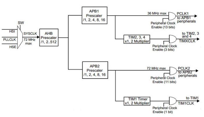
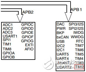
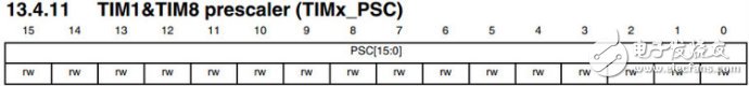
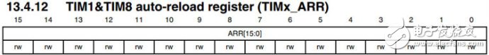
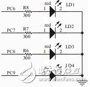
There are a total of 11 timers in STM32, including 2 advanced control timers, 4 ordinary timers and 2 basic timers, as well as 2 watchdog timers and 1 system tick timer. (TIM1 and TIM8 are advanced timers that can generate 3 pairs of PWM complementary outputs. They are often used in the drive of three-phase motors, and the clock is generated by the output of APB2; TIM2-TIM5 are ordinary timers; TIM6 and TIM7 are basic timers whose clocks generated by APB1 output) The function to be realized in this experiment is: use the ordinary timer TIM2 to generate an update event every second, and enter the state of the interrupt service routine to flip the LED1. Preliminary knowledge: ①STM32 general-purpose timer TIM2 is a 16-bit automatic reload counter. ② Up counting mode: start counting from 0, when the value in the automatic loading register (TIMx_ARR) is counted, clear to 0, and cycle in turn. Two questions to clarify: 1. What is the counting frequency of the counter? This problem involves the RCC clock part, as shown in the following figure: The clock of the timer is not directly from APB1 or APB2, but from a frequency multiplier whose input is APB1 or APB2. The function of this frequency multiplier is explained below with the clock of timers 2~7: when the prescale factor of APB1 is 1, the frequency multiplier does not work, and the clock frequency of the timer is equal to the frequency of APB1; When the frequency division factor is other values ​​(that is, the prescale factor is 2, 4, 8 or 16), this frequency multiplier works, and the clock frequency of the timer is equal to twice the frequency of APB1. Assume AHB=36MHz, because the maximum frequency allowed by APB1 is 36MHz, so the prescale factor of APB1 can take any value; when the prescale factor=1, APB1=36MHz, the clock frequency of TIM2~7=36MHz (frequency multiplication When the prescaler factor=2, APB1=18MHz, under the action of the frequency multiplier, the clock frequency of TIM2~7=36MHz. Some people may ask, since the clock frequency of TIM2~7 is required to be 36MHz, why not directly take the prescale factor of APB1=1? The answer is: APB1 not only provides clocks for TIM2~7, but also provides clocks for other peripherals; setting this frequency multiplier can ensure that when other peripherals use lower clock frequencies, TIM2~7 can still get higher Clock frequency. Another example: when AHB=72MHz, the prescale factor of APB1 must be greater than 2, because the maximum frequency of APB1 can only be 36MHz. If the prescale factor of APB1 = 2, TIM2~7 can still get a clock frequency of 72MHz because of this frequency multiplier. Being able to use a higher clock frequency undoubtedly improves the resolution of the timer, which is the original intention of designing this frequency multiplier. Note: The peripherals hanging on APB1 and APB2 are shown in the figure: There is a formula for the counting frequency of the timer: TIMx_CLK = CK_INT / (TIM_Prescaler + 1) Where: TIMx_CLK timer count frequency CK_INT Internal clock source frequency (the frequency multiplier of APB1 sends the clock) TIM_Prescaler The prescaler coefficient set by the user, the value range is 0~65535. For example: AHB=72MHZ, APB1=36MHZ, APB2=72MHZ in RCC, then CK_INT=72MKZ. 2. How to calculate the timing time? In the above formula, TIM_Prescaler involves the register TIMx_PSC If TIM_Prescaler is set to 36000, it can be seen from the above formula: The counting frequency of the timer TIMx_CLK = 72MKZ / 36000 = 2000HZ, then the counting period of the timer=1/2000HZ=0.5ms. If you want to time 1 second, you need to count 2000 times, which is also the value of automatic reload. It involves TIMx_ARR again As long as the above two problems are clarified, the rest is to set the corresponding bits of the corresponding registers. The LED hardware connection is shown in the following figure: High level lights up the LED. Step 1: Configure the system clock. See STM32F103x RCC register configuration In addition, the GPIO and TIM2 peripheral clocks need to be turned on. RCC_APB2PeriphClockCmd(RCC_APB2Periph_GPIOC, ENABLE); RCC_APB1PeriphClockCmd(RCC_APB1Periph_TIM2, ENABLE); Note: TIM2 is hung on APB1, don't make a mistake when turning on the clock, call the RCC_APB1PeriphClockCmd function instead of RCC_APB2PeriphClockCmd. Step 2: Configure the interrupt vector table. See stm32_exti (including NVIC) configuration and library function explanation void NVIC_Configuration(void) { NVIC_InitTypeDef NVIC_InitStructure; #ifdef VECT_TAB_RAM NVIC_SetVectorTable(NVIC_VectTab_RAM, 0x0); #else NVIC_SetVectorTable(NVIC_VectTab_FLASH, 0x0); #endif NVIC_PriorityGroupConfig(NVIC_PriorityGroup_1); NVIC_InitStructure.NVIC_IRQChannel = TIM2_IRQChannel; NVIC_InitStructure.NVIC_IRQChannelPreemptionPriority = 0; NVIC_InitStructure.NVIC_IRQChannelSubPriority = 4; NVIC_InitStructure.NVIC_IRQChannelCmd = ENABLE; NVIC_Init(&NVIC_InitStructure); } This function performs two functions 1. Decide whether to download the program to RAM or FLASH 2. Configure interrupt grouping. (NVIC interrupt grouping can only be set once) 3. Select the interrupt channel number, preemptive priority and response priority, and enable interrupts Step 3: Configure the GPIO mode. input mode or output mode. Lighting the LED has already been said, see STM32_GPIO configuration and library function explanation - LED marquee void GPIO_Configuration(void) { GPIO_InitTypeDef GPIO_InitStructure; GPIO_InitStructure.GPIO_Pin = GPIO_Pin_6; GPIO_InitStructure.GPIO_Speed ​​= GPIO_Speed_50MHz; GPIO_InitStructure.GPIO_Mode = GPIO_Mode_Out_PP; GPIO_Init(GPIOC, &GPIO_InitStructure); } Step 4: Timer configuration, the focus of this chapter! void TIM2_Configuration(void) { TIM_TimeBaseInitTypeDef TIM_TimeBaseStructure; //reset Timer to default value TIM_DeInit(TIM2); //Use the internal clock to provide the clock source to TIM2 TIM_InternalClockConfig(TIM2); //The prescale factor is 36000-1, so the counter clock is 72MHz/36000 = 2kHz TIM_TimeBaseStructure.TIM_Prescaler = 36000 - 1; //Set the clock division TIM_TimeBaseStructure.TIM_ClockDivision = TIM_CKD_DIV1; //Set the counter mode to count up mode TIM_TimeBaseStructure.TIM_CounterMode = TIM_CounterMode_Up; //Set the count overflow size, and generate an update event every 2000 counts TIM_TimeBaseStructure.TIM_Period = 2000; //Apply the configuration to the TIM2 TIM_TimeBaseInit(TIM2, &TIM_TimeBaseStructure); //Clear the overflow interrupt flag TIM_ClearFlag(TIM2, TIM_FLAG_Update); //Disable ARR preload buffer TIM_ARRPreloadConfig(TIM2, DISABLE); //The contents of the preload register are immediately transferred to the shadow register //Enable the interrupt of TIM2 TIM_ITConfig(TIM2, TIM_IT_Update, ENABLE); } This function performs two functions 1. Set the prescaler coefficient TIM_Prescaler = 36000 - 1 2. Set the auto-reload value TIM_Period = 2000 Note: The above only configures the TIM2, but has not opened the TIM2. The complete code of timer2.c is given below #include "stm32f10x_lib.h" void RCC_Configuration(void); void NVIC_Configuration(void); void GPIO_Configuration(void); void TIM2_Configuration(void); void Delay(vu32 nCount); int main(void) { #ifdef DEBUG debug(); #endif RCC_Configuration(); NVIC_Configuration(); GPIO_Configuration(); TIM2_Configuration(); TIM_Cmd(TIM2, ENABLE); //Turn on timer 2 while (1) { } } void RCC_Configuration(void) { ErrorStatus HSEStartUpStatus; RCC_DeInit(); RCC_HSEConfig(RCC_HSE_ON); HSEStartUpStatus = RCC_WaitForHSEStartUp() if (HSEStartUpStatus == SUCCESS) { FLASH_PrefetchBufferCmd(FLASH_PrefetchBuffer_Enable); FLASH_SetLatency(FLASH_Latency_2); RCC_HCLKConfig(RCC_SYSCLK_Div1); RCC_PCLK2Config(RCC_HCLK_Div1); RCC_PCLK1Config(RCC_HCLK_Div2); RCC_PLLConfig(RCC_PLLSource_HSE_Div1, RCC_PLLMul_9); RCC_PLLCmd(ENABLE); while(RCC_GetFlagStatus(RCC_FLAG_PLLRDY) == RESET) {} RCC_SYSCLKConfig(RCC_SYSCLKSource_PLLCLK); while(RCC_GetSYSCLKSource() != 0x08) {} } RCC_APB2PeriphClockCmd(RCC_APB2Periph_GPIOC, ENABLE); RCC_APB1PeriphClockCmd(RCC_APB1Periph_TIM2, ENABLE); } void NVIC_Configuration(void) { NVIC_InitTypeDef NVIC_InitStructure; #ifdef VECT_TAB_RAM NVIC_SetVectorTable(NVIC_VectTab_RAM, 0x0); #else NVIC_SetVectorTable(NVIC_VectTab_FLASH, 0x0); #endif NVIC_PriorityGroupConfig(NVIC_PriorityGroup_1); NVIC_InitStructure.NVIC_IRQChannel = TIM2_IRQChannel; NVIC_InitStructure.NVIC_IRQChannelPreemptionPriority = 0; NVIC_InitStructure.NVIC_IRQChannelSubPriority = 4; NVIC_InitStructure.NVIC_IRQChannelCmd = ENABLE; NVIC_Init(&NVIC_InitStructure); } void GPIO_Configuration(void) { GPIO_InitTypeDef GPIO_InitStructure; GPIO_InitStructure.GPIO_Pin = GPIO_Pin_6; GPIO_InitStructure.GPIO_Speed ​​= GPIO_Speed_50MHz; GPIO_InitStructure.GPIO_Mode = GPIO_Mode_Out_PP; GPIO_Init(GPIOC, &GPIO_InitStructure); } void TIM2_Configuration(void) { TIM_TimeBaseInitTypeDef TIM_TimeBaseStructure; //reset Timer to default value TIM_DeInit(TIM2); //Use the internal clock to provide the clock source to TIM2 TIM_InternalClockConfig(TIM2); //The prescale factor is 36000-1, so the counter clock is 72MHz/36000 = 2kHz TIM_TimeBaseStructure.TIM_Prescaler = 36000 - 1; //Set the clock division TIM_TimeBaseStructure.TIM_ClockDivision = TIM_CKD_DIV1; //Set the counter mode to count up mode
Solar lighting systems use solar cells to convert solar energy in nature into electricity and provide it to LED light sources. Due to the low voltage, energy saving and long-term characteristics of LED light sources, the application of solar LED lighting systems will achieve high energy efficiency, reliability, and practical value.
Solar panels are used to receive solar radiation during the day and convert light energy intoelectrical energy stored in the storage Battery by controller while the battery starts discharging and illuminate the light source in the evening. In the morning, the controller will switch off the battery and stop discharging according to the illuminance. The main function of the controller is to control the street lamp switch, adjust the brightness, and protect the battery to prolong the service life. Solar Lights,Solar Lights,Led Lights, Led Street Lights Wuxi Sunket New Energy Technology Co.,Ltd , https://www.sunketsolar.com