Semiconductor Fuse And Ferrite
Fuse refers to an electric appliance that, when the current exceeds the specified value, melts the fuse and disconnects the circuit with the heat generated by itself.When the current exceeds the specified value for a period of time, the fuse melts and disconnects the circuit with the heat generated by the fuse itself.A current protector made from this principle.The fuse is widely used in high and low voltage power distribution system and control system as well as power equipment.
Ferrite is a metal oxide with ferrous magnetism.As far as electrical properties are concerned, the resistivity of ferrite is much larger than that of single metal or alloy magnetic materials, and it has higher dielectric properties.Ferrite magnetic energy also shows high permeability at high frequencies.As a result, ferrite has become a non-metallic magnetic material widely used in the field of high frequency and weak current.Due to the low ferrite magnetic energy stored in the unit volume, saturated magnetic induction strength (Bs) and low (usually only pure iron 1/3 ~ 1/5), and thus limits its higher requirements in the low-frequency magnetic energy density in the field of high voltage and high power applications.
Semiconductor Fuse, Fuse Cutout, Protection Fuse, Square Fuse, Fuse Link, Ceramic Fuse, Fuse Box, Fuse Resistors YANGZHOU POSITIONING TECH CO., LTD. , https://www.cnfudatech.com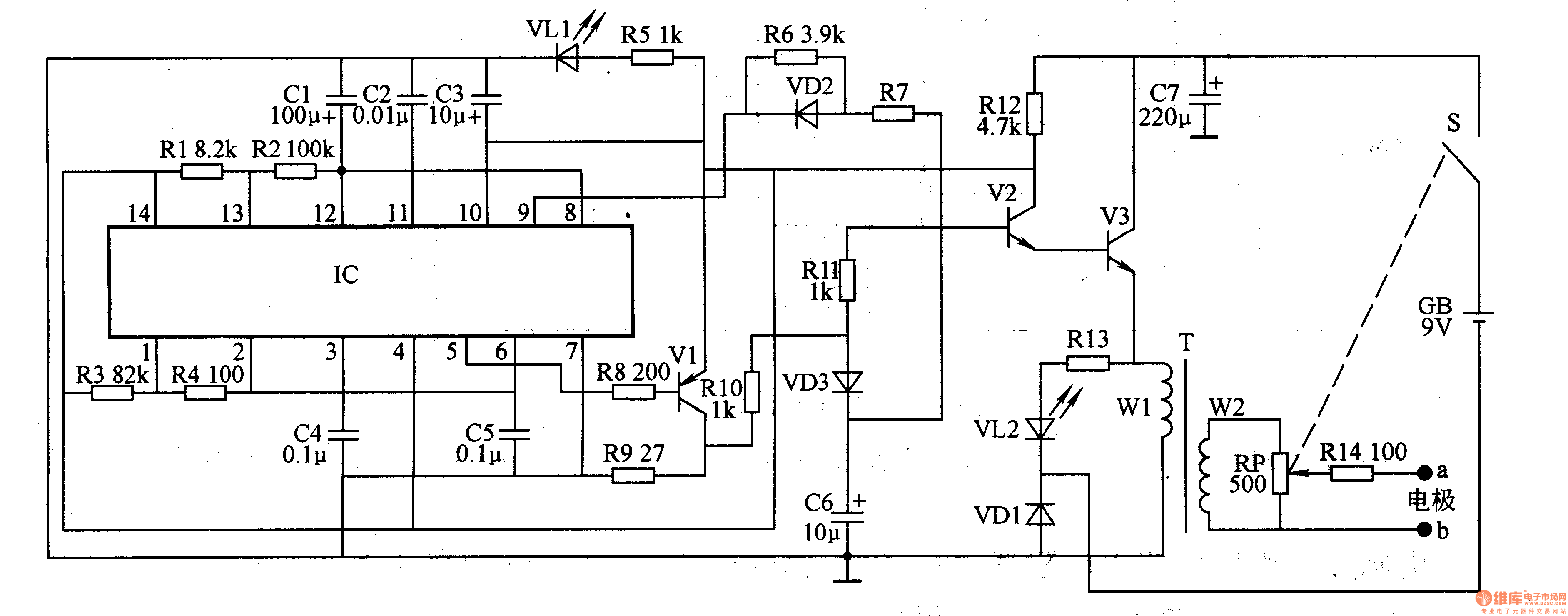
The power circuit is composed of a battery GB, a power switch, a filter capacitor C7, resistors R5 and R12, and a power indicating LED VLl.
The self-excited oscillator circuit is composed of a dual time base integrated circuit IC, a resistor Rl-R4, and a capacitor Cl-C5.
The electric pulse generating circuit is composed of a transistor V1-V3, a resistor R6-R14, a capacitor C6, a diode VD1-VD3, a light-emitting diode VL2, a pulse transformer T, a potentiometer RP, and electrodes a, b.
Turn on the power switch S, the 9V DC voltage of GB is directly supplied to V3 through VDl; the other circuit is used as the working power supply of lC, Vl and V2 after being derated by Rl2, and VLl is lit after being depressurized by R5.
The self-excited oscillator oscillates after power-on, and the oscillation pulse signal is output from the 5th pin of the IC. After the signal is amplified by V1, V2 and V3 are intermittently turned on, VL2 flashes, and a pulse voltage is generated on the winding W2 of the T. After the pulse voltage is adjusted by RP and R14, it is added to the acupuncture points of the human body through electrodes a and b, which can relieve the effects of activating and relieving pain and relieving pain.
Adjusting the resistance of the RP can change the intensity of the electrical pulse to the human body.
Component selection
Rl-R14 uses 1/4W metal film resistor or carbon film resistor.
The RP uses a small-scale synthetic carbon film potentiometer with a switch (power switch S).
Cl, C3, C6 and C7 are all made of Aluminum Electrolytic Capacitors with a withstand voltage of 16V; C2, C4 and C5 are made of monolithic capacitors or polyester capacitors.
VDl selects 1N4007 type silicon rectifier diode; VD2 and VD3 select 1N4148 type silicon switch diode.
Both VLl and VL2 use high-brightness light-emitting diodes of φ3mm.
Vl selects S9012 type silicon PNP transistor; V2 selects S9013 type silicon NPN transistor; V3 selects 3DGl21 or 2SDl509 type NPN transistor.
The IC uses the NE556 type dual time base integrated circuit.
T selects lW, the secondary voltage is 6V power transformer (use its primary winding as the W2 winding of T).
GB uses 9V laminated battery.
The electrodes a, b were made using a thin copper sheet (wrapped with gauze on the outside).