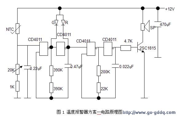
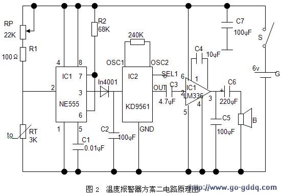
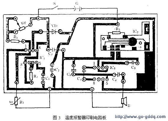
1 Introduction: Temperature is a very important physical quantity, which is of great significance for its measurement and control. With the development of modern industrial and agricultural technology and the improvement of people's living environment requirements, people also urgently need to detect and control temperature. Temperature control circuits have a wide range of applications in industrial and agricultural production. It can also be seen in daily life, such as automatic cooling of refrigerators, automatic control of air conditioners, and so on. Using a thermistor and a music integrated circuit to create a temperature alarm can also demonstrate the working principle of the automatic control circuit. The trigger end of the circuit is connected between the thermistor and the trimming resistor. When the ambient temperature rises, the resistance of the thermistor decreases, and the voltage of the trigger terminal of the circuit rises, triggering the operation of the music integrated circuit. Adjusting the resistance of the trimming resistor can change the temperature at which the circuit alarms. The three foundations of modern information technology are information collection (ie sensor technology), information transmission (communication technology) and information processing (computer technology). Sensors are at the forefront of information technology, especially temperature sensors are widely used in industrial and agricultural production, scientific research and life, and the number is the highest among all kinds of sensors. Therefore, the sensor plays an important role in the manufacture of this temperature alarm. 2 Basic introduction of temperature alarm 2.1 temperature alarm function Modern society is an information-based society. With the increasing degree of security, the computer room has become a modern hub, and its safety work has become a top priority. Once a failure occurs in the machine room, it will lead to the collapse of the entire system. The loss and social impact; Min probe company developed a computer room over-temperature alarm system, powerful. High temperature fires are caused by short circuit, overload, excessive contact resistance, high temperature or fire; static electricity generates high temperature or fire; strong electric power such as lightning causes high temperature or fire; the most important is the computer, air conditioner and other electrical equipment in the computer room. When the time is working, the equipment is aging, the air conditioner is faulty, and the temperature cannot be lowered. Therefore, the electronic products in the equipment room heat up quickly. In a short time, the temperature of the equipment room rises beyond the normal temperature of the equipment, causing the system to smash or generate a fire. The alarm system will perform its functions. This article describes a temperature alarm using a thermistor as a sensitive component. When the temperature contacted by the metal probe passes through the sensor to the switch, if the temperature exceeds a predetermined value, the switch is turned on at this time, and the alarm is connected to the alarm. The audible alarm device can emit different sounds by changing the connection of some components. In order to increase the practical effect, an indicating circuit composed of a common anode two-color luminous tube is additionally added. When the circuit does not alarm, it is green, but when it is alarm, it is red and green alternately. 2.2 Development prospects At present, the living standards of our people have improved. Some electrical products are reaching thousands of households. According to statistics, there are currently about 1.3 billion people in China. Almost every family has used boiling water tools like hot ones. What followed was an accident that was caused by improper use or use while forgetting. If the system is used in practice, it can effectively curb such accidents. Therefore, if the actual product is put on the market, it will have a large market space and broad development prospects. This product can emit different alarm sounds when connecting some connections in different ways. This product overcomes the shortcomings of the popular alarms, has low cost, and has greater practicability and novelty. The main innovations and application prospects are as follows: high sensitivity, high stability, and timely alarm. The system has high sensitivity and high stability, thanks to the system has a good sensor. But it still has certain flaws, and it has its own limitations. If a better sensor can be applied to the product, the product will have a broader development prospect. 3 temperature alarm manufacturing process 3.1 temperature alarm circuit design scheme 1 working principle design scheme 1 of the circuit diagram shown in Figure 1: The main circuit of the temperature alarm consists of NTC temperature measuring resistor, adjustable temperature potentiometer, low frequency oscillator and audio oscillator. The working principle is as follows: The temperature value is set by the potentiometer. When the temperature rises, the resistance value of the temperature measuring resistor NTC decreases, reaching the CD4011 input high-level threshold, causing the low-frequency oscillator to work, modulating the audio oscillator, and amplifying through the triode. The device sounds an alarm. 3.2 circuit design scheme 2 works The circuit of the temperature alarm is shown in Figure 2. The time base circuit IC1, the potentiometer Rp, the resistor R1 and the thermistor RT constitute a temperature detection trigger circuit. RT is a negative temperature coefficient thermistor whose resistance decreases with increasing temperature. IC2 is an audio integrated circuit KD9561, which can produce four kinds of analog sounds, namely police car sound, fire truck sound, ambulance sound and machine gun sound. IC3 is an audio power amplifier that amplifies the weak audio signal and pushes the speaker B to sound. The specific work process is as follows: When the temperature does not reach the predetermined value, since the resistance of the temperature sensor RT is greater than 1/2 (Rp+R1), the potential of the pin 2 of the trigger terminal of IC1 is higher than 1/3G (2V), so that the pin 3 of IC1 is low, the diode VD is cut off, IC2 has no audio signal output due to lack of supply voltage, and speaker B is silent. When the temperature rises to a predetermined value, the resistance of RT will be less than 1/2 (Rp+R1), the potential of pin 2 of IC1 is lower than 1/3G (2V), and the output of IC1 is low. When it goes high, the diode VD turns on and outputs a DC voltage of about 5V (200mA). The DC voltage is filtered by capacitor C2 and supplied to IC2. At this time, the siren signal generated by IC2 is output from the OUT terminal, and is coupled to the input pin 3 of IC3 via C3 for power amplification. The amplified audio signal is output from pin 5 of IC3, and finally the speaker B is driven by the capacitor C6 to emit a loud siren alarm sound. Through the comparison of various aspects of the above two options. According to the analysis of applicable prospects and market economic benefits, it is more reasonable to choose the first option. 3.3 Selection of components in the device RT selects the temperature-measuring MF53-1 negative temperature coefficient thermistor. At 25 °C, its nominal resistance is 2890 Ω ± 2%. IC1 is the NE555 time base integrated circuit, IC2 is the four-sound audio integrated circuit KD9561, and IC4 is the LM386 type power amplification integrated block. RP uses a small solid potentiometer, G is a 6V laminated dry battery, and 6V rectified power can also be used. B uses a small electric speaker with an impedance of 8 Ω and a power of 0.25W. The remaining components can be selected according to the parameters shown in the figure, no special requirements. 3.4 Production and debugging In the process of welding, in order to ensure the solder joint is firm, the contact is good and beautiful, there is no virtual welding or false welding. Before welding, use a knife, a broken saw blade or a sandpaper to scrape off or polish the oil and oxide film on the lead lead. Or paint until a bright, clean surface is exposed, then apply a rosin solution and apply a layer of tin. The temperature and time should be mastered during welding. The welding time is generally 3 to 5 seconds. If the welding time is too short, the solder is not fully immersed in the weldment, which may cause false welding or false welding. If the time is too long, the copper foil or component of the printed board will be burnt. The temperature of the soldering iron is too low, and the surface of the solder joint is rough and dull, and it is in the form of bean curd. When soldering, the soldering iron tip should be close to the lead or lead head and the pad copper foil on the printed board. When the solder joint temperature rises to the melting point of the solder, the solder melts automatically to the lead and the copper foil to form a tapered shape. Smooth solder joints, then quickly remove the soldering iron. The soldered components cannot be moved or shaken until the solder has completely cured. Solder can be melted on the tip beforehand, or it can be fed when the soldering iron is applied to the solder joint. Figure 3 shows the printed circuit of the temperature alarm. After the components are welded, it is necessary to check for leaks, solder joints, and short-circuiting of components due to soldering. It is difficult to find the virtual solder. It can be pulled gently by clamping the component pins with tweezers. If it is found to be shaken, it should be repaired immediately. This stage of debugging is the first part of debugging, that is, power-off debugging, the steps are as follows: 1) Short circuit detection system After the circuit is completed, short circuit detection must be performed. The detection method is simple, select the appropriate multimeter ohmic block, and use the red and black test leads to connect the positive and negative poles of the +5V power supply of the circuit board. If there is charge and discharge (that is, the resistance indication is from large to small and then large or small to large), finally The resistor is stable in an appropriate position. Basically, the system short circuit can be eliminated. If there is no charge or discharge phenomenon or the resistance value is stable at a small value, it means that the system may have a short circuit fault, and the power can not be tested. The system must be carefully checked until it is resolved. 2) The correctness of the principle confirms that different circuits have different working principles. Therefore, specific analysis must be performed for specific circuits. The hardware circuit design of this design has been verified in the previous circuit design, which is correct. After the above check is correct, enter the second part of the debugging is power-on debugging, the circuit principle shows that the level of the pin 2 of the trigger end of IC1 is determined by the series voltage divider circuit composed of temperature sensor RT, potentiometer RP and resistor R1. Adjusting the resistance of RP can turn IC1 over at a certain temperature to achieve the purpose of temperature alarm. The nominal value of RT is 3K. When the temperature is 50 °C, the resistance is about 950Ω, and when it is 100?C, it is about 240Ω. If the liquid is tested, a self-made temperature probe is required. The method is to first package the RT in a copper tube with a length of 100 mm and a diameter of 20 mm, and seal the ends with epoxy glue. When using, insert the temperature probe into the liquid. This circuit uses the police car sound as the alarm signal. The analog sound emitted by the KD9561 depends on the connection mode of the SEL1 and SEL2. For example, when SEL1 and SEL2 are both off, it is the police car sound. When SEL1 is connected to the negative voltage, it is the ambulance sound. When SEL2 is connected to the positive voltage, it is the machine gun sound. The entire board is placed in a small plastic case for normal use. Commutator For Electrical Hammers Motor Commutator For Electrical Hammers Motor,Control Cables For Garden Tools,Motor For Garden Tools,Generator Motor Commutator ZHEJIANG JIAGU ELECTRIC APPLIANCES CO. LTD , https://www.chinajiagu.com

