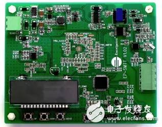
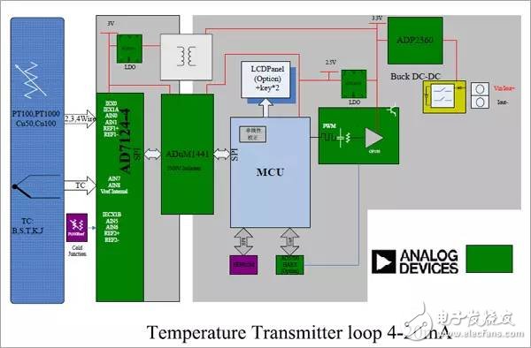
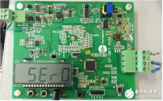
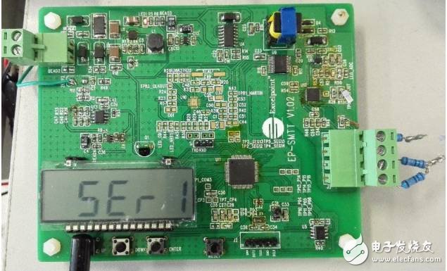
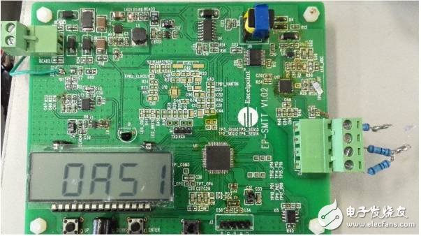
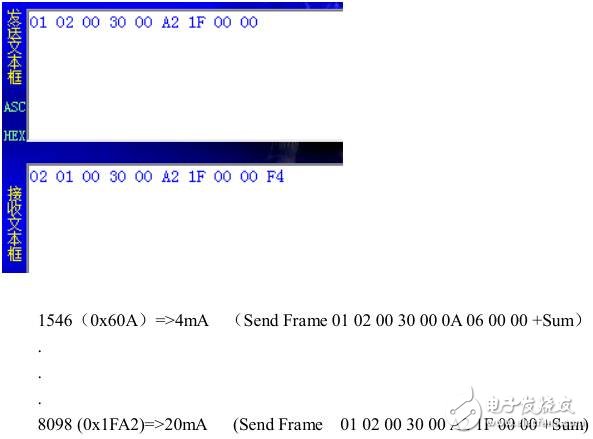
The latest and most fresh reference design is coming [Intelligent Temperature Transmitter] The [Intelligent Temperature Transmitter Reference Design ] recommended today is characterized by high precision, signal isolation, LCD display, HART protocol support, loop power supply, interface protection, etc. This platform is mainly based on ADI's self-checking function. Multi-channel ADC and EPSON's ultra-low power 16-bit MCU implementation. The main IC of this design uses the 24-bit ADC AD7124-4, which integrates a 24-bit ∑-Δ ADC, buffer and PGA (Programmable Gain Amplifier). The transmitter converts temperature (standard RTD or thermocouple) signals to a 4-20 mA signal that is output by the supply loop. For this reference design, ADI offers you: Hardware design documentation (schematic, PCB, and BOM) User operation manual The figure below shows the physical diagram of the circuit board of the reference design [Intelligent Temperature Transmitter]. 1) Power input 12V~39V DC (if high voltage TVS is replaced, Vmax should be up to 60V) Current output (loop) 4-20mA; 2) Signal input: Single thermocouple (K, T) or thermal resistance (PT100, PT1000), which can be added to other models later; 3) Communicate with a PC or IPC, Uart (J4; Txd, Rxd, Gnd) (subsequently changed to HART). *This evaluation kit provides the following interfaces: Power / 4-20mA current / Hart signal, three shared ports Sensor RTD/TC access port The mode switching is implemented by three buttons + 1 segment code lcd. The default is Run mode. The power-on display starts Initialization. If it is switched to a pure number, it enters the Run normal working mode. 1) Press ENTER: Debug (Setup) / Run mode switch Enter Debug mode to achieve 2 functions - Sensor selection Current current output, value set by Mcu serial port 2) Button UP: Sensor model scroll switch 0-9 SEr1: PT100 SEr2: PT1000 SEr8: TC-K SEr9: TC-T 3) Press DOWN: After selecting SErX and pressing OASx, the target sensor is set successfully. Just press RTD or TC to switch. Just press Reset button. If not, power on again. Press ENTER, key to enter the Debug mode. At this time, the current can be set freely. The current communication is directly output (J4) by the MCU's Uart and connected to the PC. Subsequent Hart can be output by the loop carrier. Handheld Air Mixer,Handheld Pneumatic Mixer,Portable Pneumatic Mixer,Pneumatic Air Agitator Mixer RUDONG HONGXIN MACHINERY CO.,LTD , https://www.rdhxmfr.com