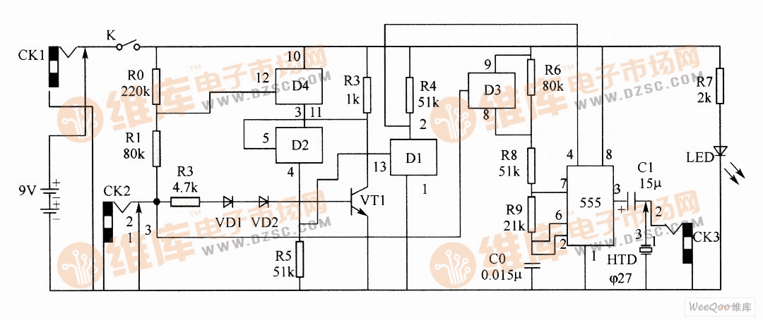
As shown in the figure, it is a multi-purpose logic pen circuit diagram composed of four bidirectional analog switches CD4066D1~D4) and 555 time base circuit, which can realize three-state audio logic pen, acoustic signal proofreader, audio signal generator and 555 time base circuit. Five functions of the monitor and the door whistle. Multipurpose logic pen circuit In the figure, D2, D4 and R5 form two input and gates, and D1 and R3, R4 and VT1 constitute a NOT gate. The 555 circuit forms a multivibrator with R8, R9, R6, C0, etc., and the be junction of VD1, VD2 and VT1 forms a reference level when measuring the logic level of the external circuit. When the positive probe is connected to a low level, f D4 is turned off, and D3 is also turned off. The oscillation frequency is: (2) Acoustic signal proofreader. Short the short pins. Indoor Led Display,Indoor Advertising Led Display Screen,Indoor Led Screen,Led Screen Indoor ShenZhen Megagem Tech Co.,Ltd , https://www.megleddisplay.com
This circuit can realize five functions.
(1) Three-state audio logic pen. Insert the plug with the double lead into CK2 and CK3 as the positive and negative poles of the logic pen. When measuring, when the treble is emitted, it indicates high level; when the bass is emitted, it indicates low level; when no sound is emitted, it indicates that it is not connected.
When the positive probe is connected to the high level and the negative probe is connected to the circuit under test, the VT1 oscillation frequency is: 

(3) Audio signal generator. The audio signal is output by CK3.
(4) 555 time base circuit detector.
(5) When using a speaker instead of a piezoelectric buzzer, it can be used as a door whistle.