High efficient charging speed for Acer laptop, stable current outlet can offer power for the laptop at the same time charge the laptop battery. The best choice for your replacement adapter. The DC connector is 5.5*1.7mm or 3.3*1.0mm. We can meet your specific requirement of the products, like label design. The plug type is US/UK/AU/EU. The material of this product is PC+ABS. All condition of our product is 100% brand new.
Our products built with input/output overvoltage protection, input/output overcurrent protection, over temperature protection, over power protection and short circuit protection. You can send more details of this product, so that we can offer best service to you!
Laptop Adapter For Acer,Charger For Acer,Acer Laptop Adapter ,Ac Adapter For Acer Shenzhen Waweis Technology Co., Ltd. , https://www.waweisasdapter.com
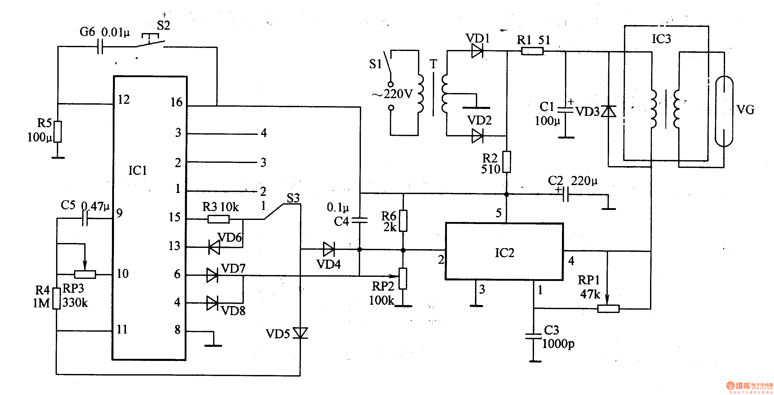
The power circuit is composed of a power switch S1, a power transformer T, rectifier diodes VD1, VD2, resistors R1 and R2, and capacitors C1 and C2.
The timing control circuit is composed of a timer integrated circuit ICl, a resistor R3-R5, a potentiometer RP3, a capacitor C4-C6, a diode VD4-VD8, a gate switch S2, and a timing selection switch S3.
The high voltage circuit is composed of a capacitor è‰, a C3, a resistor R6, a potentiometer RP1, an R-tooth and an electronic switch integrated circuit IC2, a diode VD3, a boosting module IC3, and an ozone tube VG.
The AC 220V voltage is rectified by T step-down, VD1 and VD2 to generate l2V DC voltage. One channel is supplied to the boost module IC3 through R1 current limit and Cl filter; the other channel is supplied to lCl and IC2 through R2 current limit and C2 filter.
When the timing time has not expired, VD4 and VD5 are in the off state due to the positive terminal being low level, and the oscillator composed of IC2 and RP1, C3 and the like oscillates to generate an oscillation signal of l5 kHz, and a pulse high voltage is generated by the boosting module IC3. Ozone is generated by the ozone tube VG. When the timing time is over, VD4 and VD5 are turned on, the oscillator stops, and the high voltage on the VG disappears.
S3 is used to select the timing time. When S3 is placed in the "1" position, the timing is 5min; when S3 is placed in the "2" position, the timing is 15min; when S3 is placed in the "3" position, the timing is 30min; When placed in the "4" position, the timing is 60min.
Adjust the resistance of RPl so that the operating frequency of the oscillator in the high-voltage circuit is l5kHz; adjust the resistance of RP2 so that the voltage of pin 2 of IC2 is less than or equal to 1·2V; adjust the resistance of RP3 to make the built-in oscillation of the timer circuit The frequency of the device is 2.3 Hz.
Component selection
Rl-R6 uses 1/4W metal film resistor or carbon film resistor.
RPl-RP3 uses ultra-small synthetic carbon film potentiometer or variable resistor.
Both Cl and C2 use aluminum electrolytic capacitors with a withstand voltage of i6V; C3-C6 uses monolithic capacitors or polyester capacitors.
VDl-VD3 selects lN4007 type silicon rectifier diode for use; VD4-VD8 selects 1N4148 type silicon switch diode for use.
ICl selects CD4060 type timer integrated circuit; lC2 selects WVH8751 type electronic switch integrated circuit; IC3 selects Dahua TWH boost module.
T selects 3-5W, the secondary voltage is l2V power transformer with center tap.
S1 selects AC and 220V AC power switch; S2 uses small micro switch (if the waste single door refrigerator is used as the sterilizer chassis, the original refrigerator door switch can be used); S3 selects the small single-pole four-position switch .
VG uses T90 type bipolar ozone tube.