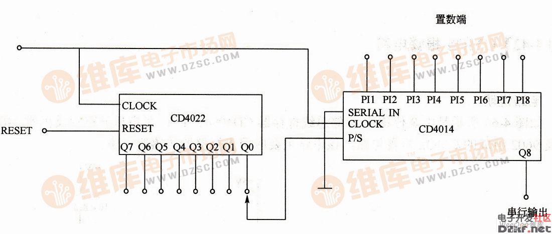
As shown in the figure is a parallel-serial data conversion circuit consisting of an 8-bit serial/integration-to-serial shift register CD4014 and an octal counter/distributor CD4022, which is often used for parallel-serial in digital systems. Output data conversion. Parallel-serial data conversion circuit In the data conversion process, parallel data is added to PI1 to PI8 of CD4014, and serial data is output by Q8. The P/S end of CD4014 is connected to the Q0 end of CD4022. A positive pulse is applied to the CLOCK terminal to make the Q0 terminal of the CD4022 output a high level, and the P/S terminal of the CD4014 is a high level to perform parallel operation. Under the action of CLOCK, PI1~PI8 are sent to the register. At this time, the Q0 end of CD4022 changes from high level to low level, which turns CD4014 into serial. Continuous input of CLOCK, serial output can be obtained by Q8. This continues to convert parallel data into serial data. Shenzhen Jinziming Electronic Technology Co.,LTD , https://www.powerchargerusb.com