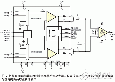
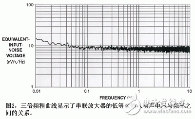
Certain medical and scientific instrument applications require amplification and measurement of microvolt-level signals. For example, to accurately measure the output of a micro-calorimeter based on a thermocouple, an amplifier that achieves very high gain and exhibits excellent thermal stability and low noise is required. Figure 1 shows how the combination of two amplifiers produces a programmable gain amplifier that provides selectable gains of 160 ~ 10240. The circuit also provides a 5mV typical offset voltage, 20 nV / ° C offset drift, and 9 nV equivalent input noise voltage at 0.1 Hz. IC1 is a Cirrus Logic CS3301 low voltage, differential input, differential output, clipper drift compensation programmable gain amplifier, which acts as an input amplification stage and drives IC2, the higher voltage INA114 instrumentation amplifier output stage. The CS3301 provides seven programmable gains ranging from 1 to 64, while the INA114 provides a fixed gain of 160. This combination achieves a gain of 160 ~ 10240. The thermocouple generates a 1mV signal and produces a 10.24V output from the INA114. To select other gain values, change the value of the gain setting resistor R3 of INA114. The external DIP switch and pull-up resistor are connected to a 3.3V power supply (not shown), and the gain control pin and multiplexer control pin of the CS3301 are programmed. A microcontroller that can drive a 3.3V logic circuit can also control these control inputs. Connect the output terminal of CS3301 and the input terminal of INA114, an RC low-pass filter composed of R1, R2, IC1 output resistor and C1, can limit the noise higher than 500Hz. Figure 2 shows the input reference noise performance measurements of these combined amplifiers at a gain of 10,000. The 1 / f noise corner of the series combination of this amplifier is 0.08 Hz, and the equivalent input noise voltage at 0.1 Hz is about 9 nV. The noise versus frequency curve shows the result of FFT processing of more than 2 million output samples during 18 hours. For simplicity, the schematic does not show the power supply and bypass capacitors. Because the amplification factor of this circuit is extremely large, the construction techniques used should keep the components placed thermally balanced and the length of the printed circuit traces electrically balanced.
Features of Kassel Servo Motor high speed:
1. Constant torque output, low energy loss
2. Lighter, more compact and more efficient
3. With the servo vector algorithm, precise positioning can be achieved
4. Strong environmental adaptability, strong overload capacity, safe and reliable
Kassel servo motor high speed application:
Aerospace satellites, military weapons and equipment, biomedical, extreme environments, automation equipment, automobile assembly
Servo Motor High Speed,Servo Motor High Torque Low Rpm,High Speed High Torque Servo Motor,Parallax High Speed Continuous Rotation Servo Kassel Machinery (zhejiang) Co., Ltd. , https://www.kasselservo.com
