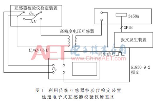
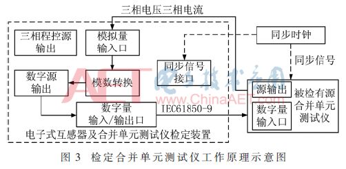
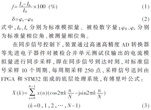
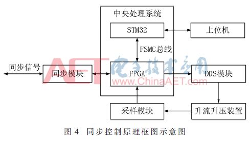
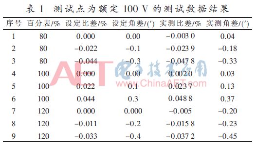
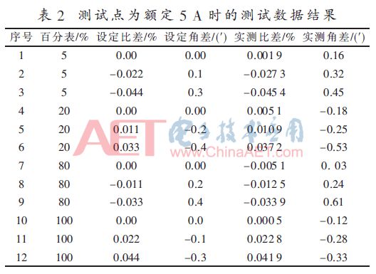
Electronic transformers and merging units are the core components of intelligent substations. Its performance and accuracy and other indicators have a decisive impact on relay protection, measurement and control, and digital energy measurement. The power supply units in various regions have a decisive influence on electronic transformers and merging units. The measures or methods adopted in the links of model selection, acceptance, and regular inspection have not yet reached the level of perfection, comprehensiveness and accuracy. A value traceability device for a combined unit tester is proposed, which has the characteristics of integrated and separable structure of meter and source. It can trace the value of the electronic transformer calibrator and the combined unit tester, and can also directly calibrate the electronic mutual inductance. The error of the converter and the merging unit. 0 Preface For the verification of electronic transformers, the main sources of measurement uncertainty are standard transformers and electronic transformer calibrators. Standard transformers have a very complete traceability system, and there are many problems with the traceability of electronic transformer calibrators. . Since the working principle and output mode of electronic transformers are very different from traditional transformers, the verification of electronic transformers cannot use traditional transformer verification methods [1]. The merging unit receives the sampled value and outputs the digital message according to the IEC61850-9-2 [2] standard. Therefore, the focus of the test is to test its sampling accuracy and data synchronization performance [3]. This paper analyzes the research status and existing problems of similar error traceability technologies at home and abroad, and proposes a value traceability device for a combined unit tester, and expounds its working principle and practical application methods. 1 Digital background The smart grid requires the digitization of the information of the entire substation, the networking of the communication platform, and the standardization of information sharing [4]. Electronic transformers and merging units are the core components of smart substations, and their performance and accuracy and other indicators have a decisive impact on relay protection, measurement and control, and digital power measurement. The merging unit first appeared in the IEC 60044-8 electronic current transformer standard. It is a physical unit that collects and processes the data of the secondary converter and provides relevant data samples for the secondary equipment. The merging unit can be a field transformer A component or independent unit [5]. However, the measures or measures taken by the power supply departments of various regions in the selection, acceptance, and regular inspection of electronic transformers and merging units have not yet reached the level of perfection, comprehensiveness and accuracy. At the same time, the marketing department of the State Grid Corporation issued a statement in April 2016. Issued a notice on the development of research work on the construction of a digital measurement system, emphasizing the need to strengthen the construction of digital standard equipment, vigorously carry out research on the traceability technology of digital measurement equipment, and propose to establish a complete digital measurement management system within the company in 2020. It meets the requirements of trade settlement in terms of degree, stability, and traceability. 2 Research status at home and abroad The research on electronic transformer testing technology at home and abroad is relatively early, but it is limited to the most basic error measurement requirements, and the verification of the testing instrument only depends on the detection of several 8.5-digit multimeters such as HP3458A, because the 3458A multimeter was designed 30 years ago. Although the DC index is very good, there is no accurate definition of sampling delay, so this method is very limited. The foreign measurement technology for the error of the combined unit and the electronic transformer lags behind the domestic development, and is still in a split combination system. In the experiment, various messages and synchronization signals are relatively simple. The domestic testing technology for electronic transformers and merging units originated from around 2005. Various 61850 standard messages and corresponding extended messages are widely used in the State Grid and China Southern Power Grid, and the corresponding measurement adaptive technology is also very good. development of. The traceability method adopted at this stage has certain limitations. In terms of electronic transformer verification, the main sources of measurement uncertainty [6] are standard transformers and electronic transformer calibrators. Standard transformers have a very complete traceability system, but there are many problems in the traceability of electronic transformer calibrators. At present, the mainstream method is to use a system that combines traditional transformer calibrator verification devices and 3458A digital multimeters, referred to as analog micro difference. Source method, see Figure 1. The main disadvantage is that the traditional overall verification device for transformers uses the principle of differential measurement based on the Cartesian coordinate system [7], and electronic transformers cannot perform differential measurement. There will be a certain theoretical error when the angle difference is, and the error is proportional to the cosine value of the angle difference. For this reason, it is very necessary and meaningful to establish a set of high-level electronic transformer calibrator and combined unit tester traceability benchmark based on the polar coordinate system. The research device described in this article-electronic transformer calibrator and combined unit tester traceability device, to perform metrological verification of all electronic transformers and combined unit testers of level 0.05 and below, and can also take into account the level of 0.2 and below Electronic transformers and merging units are tested, so as to establish a complete digital metrological verification system ranging from 0.01 to 0.2. 3 Principles of device scheme design The inherent delay error of the sampling system is the main factor of the phase error of the electronic transformer calibrator [8]. Both the phase offset and the delay time will cause the phase error, which can be corrected by the phase compensation link [9]. The device described in this article achieves accurate measurement and control of phase through accurate synchronization signal control technology. The design of the traceability device of the combined unit tester mainly has the following technical difficulties: (1) Precise measurement of the effective value of 0.01 level voltage and current fundamental wave; (2) The zero-crossing signal is precisely controllable; (3) High-precision data consistency under multiple synchronization signals. The device described in this article adopts an embedded system design and is divided into two major modules, the bottom layer and the background layer. The bottom layer is composed of FPGA and STM32 as the core. The background layer is composed of the hardware foundation of the ARM9 system. The software adopts the Linux system and uses 24-bit multi-channel high-precision AD converter , Analog sampling with more than 200 points per cycle and window function compensation algorithm, DDS extremely low distortion digital source design with zero-crossing pulse delay error within 100 ns, synchronization signal control technology, etc., make the device meet the high-level use requirements. 3.1 Overall design The system mainly includes a high-precision three-phase digital program-controlled source, a multi-channel analog measurement module, a synchronous signal transceiver, an Ethernet data message transceiver, a Fourier window compensation algorithm, and a non-synchronous error measurement technology module. The overall structure diagram of the design device is shown in Figure 2. The built-in three-phase source conforms to the integral separable structure of the meter source, and you can choose to use the built-in source or external source when working; the design of the multi-channel analog sampling module and the Fourier window compensation function can be effective for the 0.01-level voltage and current fundamental wave Precision measurement of the value; accurate synchronization signal control technology is the core of phase measurement and control. 3.2 Principle of device standard error Taking the verification of the combined unit tester as an example, combined with the measurement principle of the ratio difference and angle difference of the current to the digital quantity, the realization of the error measurement of the traceability device of the combined unit tester is explained. The voltage function is similar to the current measurement. The principle block diagram of the verification combined unit tester is shown in Figure 3. When verifying the combined unit tester, the analog output of the tested combined unit tester is used as the standard signal and connected to the analog input interface of the device; the digital output of the device is used as the tested signal and connected to the tested combined unit tester. Digital interface. At the same time, pre-set ratio and angle difference on this device. After synchronously sampling the standard analog quantity, the device outputs the digital message superimposed with the ratio difference and the angle difference as the measured signal to be connected to the tested merging unit tester, so as to perform error verification on the merging unit tester. Suppose the output current of the combined unit tester under test is a standard analog quantity, and the digital message output by this device is regarded as a digital quantity under test. According to the definition of ratio difference f and angle difference δ: In the formula, x(n) is the effective long sequence, N is the number of samples, n is the number of cycles, and k takes the value [0, N-1]. According to formula (3), the effective value and initial phase angle of the current at the zero crossing time are restored; the effective value and initial phase angle of the restored standard signal are superimposed on the preset ratio difference and phase difference, thereby generating the measured digital quantity Effective value and phase angle, according to IEC61850 protocol, under the control of synchronization signal, the device outputs a digital message superimposed with a ratio difference f and an angle difference δ. According to the result of the Fourier algorithm, the standard current analog quantity I0 can be expressed as: In the formula, I0 is the standard current analog quantity, A is the amplitude, ω is the angular frequency, θ is the initial phase angle, and t is the time. Then the measured signal Ix with the error superimposed can be expressed as: In the formula, Ix is the measured signal after superposition error, f is the ratio difference, and δ is the angle difference. According to the generated new sine function sequence, the digital message required by the merging unit is calculated, and the ratio difference and phase difference on the tester software of the detected merging unit are observed in real time, and compared with the ratio difference and phase difference set by the software of the device. Furthermore, error verification can be performed on the combined unit tester. 3.3 Synchronous control technology For devices that require a phase accuracy of 0.3 cents as a whole, accurately measuring the phase and compensating for it is a necessary means to ensure that the phase error uncertainty of the device reaches the standard. The core of phase measurement is accurate synchronization control technology. Using the generation mechanism of the programmable signal source DDS, the FPGA generates the second pulse synchronization signal related to the phase error. According to the synchronization signal, the sampling module synchronously samples the standard analog signal, and the sampled value is sent back to the central processing system composed of FPGA and STM32 to analyze the effective value and phase of the standard analog signal at the time of zero crossing, thereby realizing accurate phase measurement. Synchronous signal control technology is also applied to phase measurement compensation of three-phase sources. Since the DDS source only has a voltage range of a few volts, it will inevitably cause a phase shift after being converted into a current of 0~6 A and a voltage of 0~120 V. Through synchronous control technology, the actual output angle and synchronization signal of the three-phase source can be analyzed. Re-adjust the configuration parameters to accurately measure and compensate the phase shift after boosting or current boosting. The principle block diagram of synchronous control technology is shown in Figure 4. 4 Measured data The traditional traceability system with 3458A as the core compares and calibrates this device to obtain the following sets of data. It can be seen that as a new traceability system, this device can be compared with traditional devices in terms of data accuracy and stability. It is more advantageous in terms of diversity and ease of use. 4.1 Voltage vs. Digital An induction voltage divider + 3458A meter is used to form a standard sampling system, which receives the synchronous output of this device. The computer data analysis adopts the Fourier algorithm. Table 1 shows the test data when the test point is rated at 100 V. 4.2 Current vs. Digital The shunt + 3458A meter is used to form a standard sampling system, and the synchronous output of this device is received. The computer data analysis adopts the Fourier algorithm. Table 2 shows the test data when the test point is rated at 5 A. 5 Conclusion Through the technical research of the above aspects, the traceability device of the combined unit tester designed in this paper has the following innovations: (1) It adopts a detachable structure of the meter and the source, which can output the standard source and the digital message signal under test, and can also receive it. External standard source and external input data message; (2) Using precise synchronization control technology to achieve accurate phase measurement and compensation. The traceability device of the combined unit tester can be used as a benchmark for synchronous and asynchronous verification of the electronic transformer calibrator and combined unit tester of level 0.05 and below, and can be used as a common electronic transformer calibrator and merging unit at the same time The tester tests the electronic transformers or merging units, and then establishes a 0.01-level metrological verification system.
Withstand high voltage up to 750V (IEC/EN standard)
UL 94V-2 or UL 94V-0 flame retardant housing
Anti-falling screws
Optional wire protection
1~12 poles, dividable as requested
Maximum wiring capacity of 25 mm2
25 mm2 connector blocks, 60 amp Terminal Blocks,traditional screw type terminal blocks,Pa66 Terminal Blocks Jiangmen Krealux Electrical Appliances Co.,Ltd. , https://www.krealux-online.com