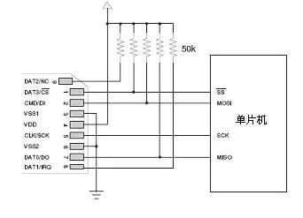
SD card pin definition: Note: S: Power Supply I: Input O: Push-pull driven output PP: Push-pull driven input and output SD card supports two bus ways: SD mode and SPI mode. The SD mode is a standard way of reading and writing to the SD card. However, when the SD mode is selected, an MCU with an SD card controller interface is often required, or an additional SD card control unit must be added to support reading and writing of the SD card. However, many 51-chip microcomputers do not have an integrated SD card controller interface. If SD-mode communication is used, the hardware cost of the product is virtually increased. In the case of SD card data read and write time requirements are not very strict, the choice of SPI mode can be said to be an optimal solution. I use software to simulate SPI bus timing reading and writing SD card. Among them, SD mode adopts 6-wire system and uses CLK, CMD, DAT0~DAT3 for data communication. The SPI method uses a 4-wire system and uses CS, CLK, DataIn, and DataOut for data communications. The data transmission speed in the SD mode is faster than that in the SPI mode. Generally, the SPI mode is adopted when the SCM is used to read and write the SD card. Different initialization methods can make SD card work in SD mode or SPI mode. Only the SPI method is introduced here. SD card connection mode with the microcontroller in SPI mode: SD card working voltage range is 2.0-3.6V The logic level of the IO of the SD card is 3.3V. The figure above is only suitable for the MCU logic level 3.3V. If we are using a 5V MCU we will have to do a level shift. (The following method is more insurance, and some people use resistor divider) To solve the level compatibility problem of logic device interfaces, there are two main principles: The minimum voltage level at which the output level device outputs a high level should be greater than the lowest voltage level that the receiving level device recognizes as a high level; Second, the output voltage of the output level device should be less than the highest voltage value recognized by the receiver device as a low level. Taking into account the SD card in the SPI protocol mode of operation, communications are unidirectional, so the microcontroller to the SD card to use data transfer transistor pull resistance method program, and the SD card to the microcontroller can directly connect the data transmission Because the level between them just meets the above-mentioned level-compatible principle, it is both economical and practical. This hardware connection is completed, pay attention to the working voltage of the SD card 48V15Ah Lithium Ion Battery,48V15Ah Lithium Battery Pack,Li-Ion 48V15Ah Lithium Battery Pack,Echargeable Lithium Battery Pack 48V Jiangsu Zhitai New Energy Technology Co.,Ltd , https://www.jszhitaienergy.com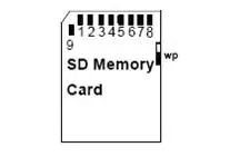
Pin number SD mode SPI mode name Types of description name Types of description 1 CD/DAT3 IO or PP Card detection /
Data Line 3 #CS I Chip Select 2 CMD PP command/
Response DI I data input 3 VSS1 S Power ground VSS S Power ground 4 VDD S power supply VDD S power supply 5 CLK I clock SCLK I clock 6 VSS2 S Power ground VSS2 S Power ground 7 DAT0 IO or PP Data line 0 DO O or PP Data output 8 DAT1 IO or PP Data Line 1 RSV 9 DAT2 IO or PP Data Line 2 RSV