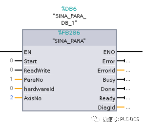
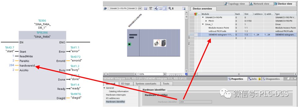
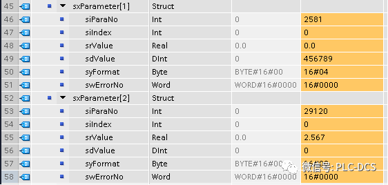
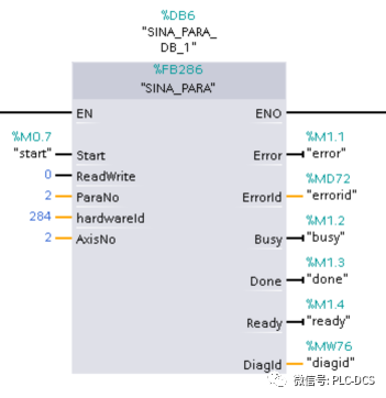
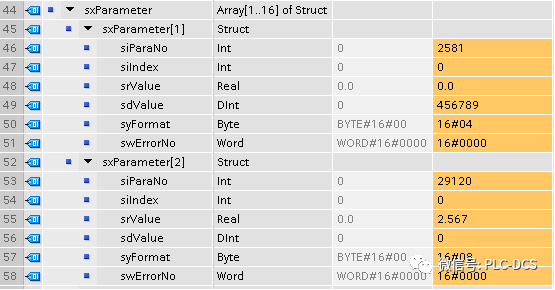
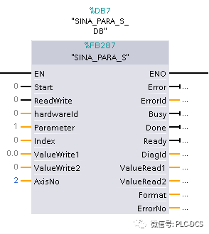
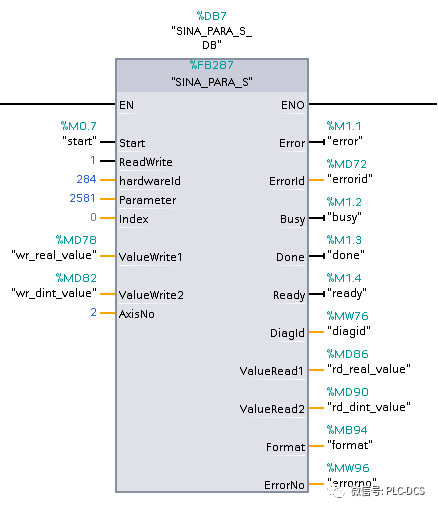
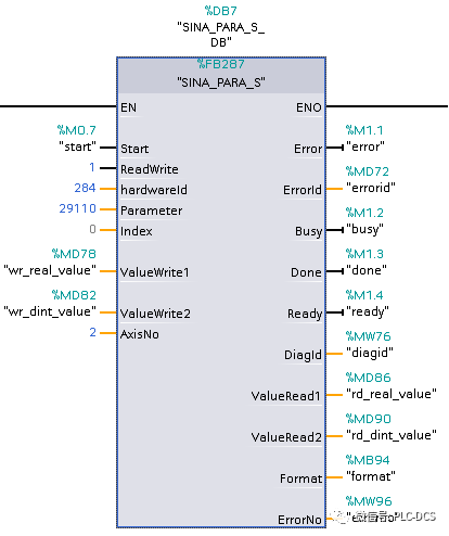
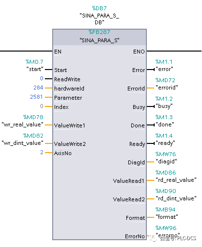
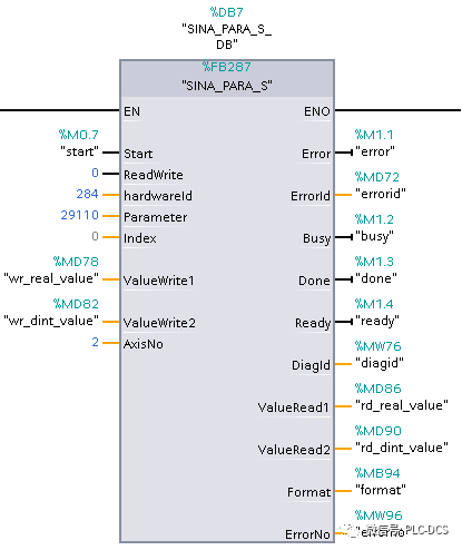
1. Read and write multiple parameters through FB286: Parameter description: 1. Start: The parameter rising operation will start the parameter operation task during the parameter operation. 2. ReadWrite: Parameter = 0 indicates a read operation, if equal to 1 corresponds to a write operation. 3. ParaNo: The number of read and write parameters, ranging from 1 to 16. 4, hardwareID: hardware identifier. 5. AxisNo: drive number, V90PN needs to be set to 2. 6. Error: Error flag. 7, Errorid: return value. 8. BUSY: 1 when the write parameter is executed, and 0 if it is completed or after the fault. 9. DONE: The task execution is completed and can be used to reset the request when writing the program. 10. Ready: The block does not perform a read or write operation and is in a ready state. 11, DiagId: return value. 1.1 Write parameter operation example: 1.1.1 Write two parameters P2581 (integer) and P29120 (real type) through FB286. The hardwareid is obtained in the hardware configuration. The FB286 interface settings are shown in Figure 1: figure 1 1.1.2 This example sets P2581=456789, P29120=2.567 through sxParameter[1] and sxParameter[2] in the SINA_PARA background data block. Note the setting of srValue and sdValue, the integer parameters are written to the sdValue variable, and the real parameters are Then write the srValue variable. If the parameter has a subscript, it needs to be set in sindex. The specific settings are shown in Figure 2: figure 2 1.1.3 Set the Start pin 0->1 and keep the parameters to be written complete. 1.2 read parameter examples 1.2.1 Read the two parameters P2581 (integer) and P29120 (real type) through FB286. The FB286 interface is set as shown in Figure 3: image 3 1.2.2 This example reads P2581=456789, P29120=2.567 through sxParameter[1] and sxParameter[2] in the SINA_PARA instance data block. Pay attention to the settings of srValue and sdValue, the integer parameters are stored in the sdValue variable, and the real parameters are stored in the srValue variable. The specific settings are shown in Figure 4: Figure 4 1.2.3 Set the Start pin 0->1 and keep the parameters to be read completed. 2. Read and write individual parameters through FB287: Parameter description: 1. Start: The parameter rising operation will start the parameter operation task during the parameter operation. 2. ReadWrite: Parameter = 0 indicates a read operation, if equal to 1 corresponds to a write operation. 3. HardwareID: Hardware identifier. 4, Parameter: parameter number that needs to be read and written. 5, INDEX: parameter subscript. 6, ValueWrite1: Here the real parameter value. 7, ValueWrite2: Here to write the integer parameter values. 8, AxisNo: drive number, V90PN must be set to 2. 9, ERROR: error flag. 10. ErrorID: The return value. 11. BUSY: 1 when the write parameter is executed, and 0 if it is completed or after the fault. 12. DONE: The task execution is completed and can be used to reset the request when writing the program. 13. Ready: The block does not perform a read or write operation and is in a ready state. 14, DiagId: return value. 15, ValueRead1: Read the real parameter values ​​here. 16, ValueRead2: Read the integer parameter values ​​here. 17, Format: The format of the parameters read. 18. ErroNo: Error code. 2.1 write parameter examples 2.1.1 Write P2581 (integer) = 12345 via FB287. Write the parameter value to be set to the variable "wr_dint_value"=12345, and set the Start pin 0->1 and keep the parameters to be written completed. The FB287 interface settings are shown in Figure 5: Figure 5 2.1.2 Write P29110 (real) = 1.234 via FB287. Write the parameter value to be set to the variable "wr_real_value" = 1.234, and set the Start pin 0->1 and keep the parameters to be written completed. The FB287 interface settings are shown in Figure 6: Figure 6 2.2 read parameter examples 2.2.1 Read P2581 (integer) = 12345 by FB287. By setting the Start pin 0->1 and keeping the parameters to be read completed, the read parameter value is written to the variable "rd_dint_value" = 12345. The FB287 interface settings are shown in Figure 7: Figure 7 2.2.2 Read P29110 (real) = 1.234 by FB287. By setting the Start pin 0->1 and keeping the parameters to be read, the read parameter value is written to the variable "rd_real_value"=1.234. The FB287 interface settings are shown in Figure 8: Figure 8
Absolute rotary Encoder measure actual position by generating unique digital codes or bits (instead of pulses) that represent the encoder`s actual position. Single turn absolute encoders output codes that are repeated every full revolution and do not output data to indicate how many revolutions have been made. Multi-turn absolute encoders output a unique code for each shaft position through every rotation, up to 4096 revolutions. Unlike incremental encoders, absolute encoders will retain correct position even if power fails without homing at startup.
Absolute Encoder,Through Hollow Encoder,Absolute Encoder 13 Bit,14 Bit Optical Rotary Encoder Jilin Lander Intelligent Technology Co., Ltd , https://www.jilinlandermotor.com