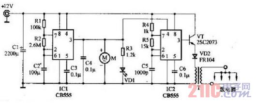
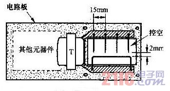
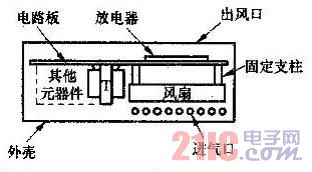
The 555 time base circuit IC2 and R4, R5, C5, etc. form a multivibrator. After the power is turned on, the IC2 output (3 pin) is high and 12V at the same time because the voltage on C5 is very low. The voltage is charged to C5 via R4 and R5, and the voltage on C5 is gradually increased. When the voltage on C5 rises to 2/3VCC, the internal flip-flop of IC2 flips, the 3-pin outputs low level, and the internal discharge tube turns on. The voltage on C5 starts to discharge through R5 through 7 feet. When the voltage on C5 drops to 1/3Vcc, the internal flip-flop of IC2 flips again, the 3-pin outputs a high level, and the internal discharge tube is turned off, and the 12V voltage is charged to C5 via R4. and R5. The oscillation is formed in this cycle, the oscillation frequency is .f=1.44/[(R4+2R5)C5], and the output of the 3 pin is about 48k. High frequency pulse voltage of Hz. This article refers to the address: http:// When the output of IC2 (pin 3) is high, the switching transistor VT is turned on, and the 12V power supply flows through the primary winding of the transformer T through the diode VD. When the output of IC2 (pin 3) is low, the switching transistor VT is turned off, and the energy stored in the transformer T is released through its secondary. Since the initial and secondary voltage transformation ratio of T is 1:300, the secondary pulse voltage will be as high as 3000V. In the above, negative ions are generated by ionizing the discharge by the tip discharge of the discharger. The role of the fan M is to allow negative ions to diffuse faster and better into the surrounding air. 555 time base circuit IC1 and R1, R2, C2 ultra-low frequency oscillator, the oscillation period is about 6 minutes, and its output terminal (3 feet) outputs a square wave with a pulse width of 180 seconds and an interval of 180 seconds. The reset terminal (4 pin) of the high-frequency oscillator IC2 is controlled by the IC1 output terminal (3 pins): IC2 oscillates when the IC1 output terminal is high level; IC2 stops when the IC1 output terminal is low level, and the IC2 output terminal is Low level. As a result of the interaction of IC1 and IC2, the circuit operates for 3 minutes, pauses for 3 minutes, and intermittently generates negative ions. The fan motor M is also controlled by the output of IC1 and works synchronously with IC2. The light emitting diode VD1 is an operation indicator of the negative ion generating circuit. It is composed of another multivibrator, which is an ultra-low frequency oscillator with an oscillation period of about 6 minutes. Its output (3 feet) outputs a square wave with a pulse width of 180 seconds and an interval of 180 seconds. The reset terminal (4 pin) of the high-frequency oscillator IC2 is controlled by the IC1 output terminal (3 pins): IC2 oscillates when the IC1 output terminal is high level; IC2 stops when the IC1 output terminal is low level, and the IC2 output terminal is Low level. As a result of the interaction of IC1 and IC2, the circuit operates for 3 minutes, pauses for 3 minutes, and intermittently generates negative ions. The fan motor M is also controlled by the output of IC1 and works synchronously with IC2. The light emitting diode VD1 is an operation indicator of the negative ion generating circuit. Component selection IC1, IC2 select two time base circuit CB555, or choose a dual time base circuit CB556. Note that the CMOS time base circuit CB7555 or CB7556 is not suitable for this unit due to its small drive current. The switch tube VT uses a medium power tube such as 2SC2073. The diode VD2 uses a fast recovery rectifier such as FR104. The fan M can be used with a cooling fan for computer CPUs of about 12V and 150mA. Its small size, thin thickness and low noise are suitable for this production. It can also be used with a 12V toy motor with a self-made fan blade. The transformer T needs to be wound by itself. The N27 type E-shaped ferrite core is used. The coil is wound around its insulating frame. The primary is wrapped with a diameter of 0.4mm and the enameled wire is wound around 11 times. The secondary is wound with a diameter of 0.1mm. The wire is wound around 3300 times. There should be an insulating layer between the layers, and the coils should be wrapped with insulating tape. As shown in the figure on the right, the discharger is made up of a circuit board. The transformer T and other components are installed on the left side, and the middle right side is hollowed out. One copper foil is connected to the secondary of T. The discharge electrode was four bare copper wires having a diameter of 0.6 mm and a length of 10 mm, and the tip was sharpened. Four discharge electrodes were welded to the upper copper foil strips at a pitch of about 15 mm. The common electrode is a bare copper wire having a diameter of about 1 mm, which is bent into a "â”â”┑┎┑" shape as shown in Fig. 3 and welded to the underlying copper foil strip. The tip of each discharge electrode is 2 mm from the common electrode. The fan M is fixed under the circuit board, and the center of the fan is facing the discharger, which is about 15 mm apart. The fan should be directed upwards to blow the negative ions generated by the arrester up into the air. The whole machine should be installed in the insulating casing. On the outer casing, some holes are opened as the air outlets at the position of the arrester, and the holes are opened at the sides of the casing near the fan as the air inlets. The 12V power cord is connected to the car cigarette lighter plug. Uv Curing Film For Mobile Tablet Uv Curing Film For Mobile Tablet,Tempered Glass For Mobile,Phone Curve Edge Protector,Local Tempered Glass Shenzhen TUOLI Electronic Technology Co., Ltd. , https://www.hydrogelprotectors.com

