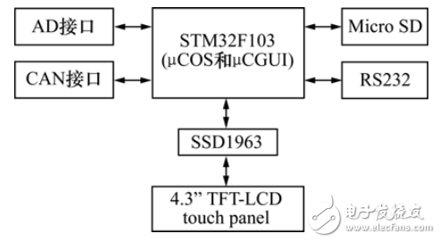
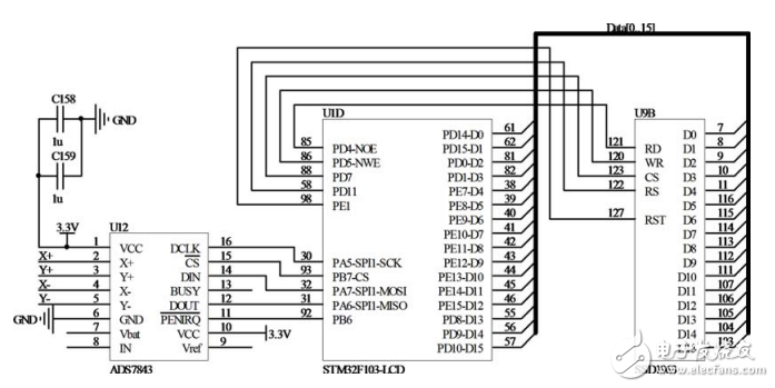
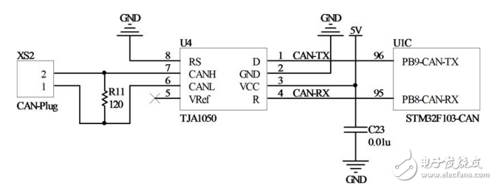
The measurement and control system is an important test equipment in hydrodynamic experiments. In the experiment, physical quantities such as pressure, tension, and acceleration are converted into voltage values ​​by sensors, and accurate recording is required. Although there are many experimental models, the sensors and measurement and control systems are shared, so the requirements for the versatility and user-friendliness of the measurement and control system are put forward. This paper designs the measurement and control system with embedded architecture. The system hardware designed in this paper is based on STM32 chip, has strong expansion capability, is easy to transplant, and has abundant peripheral unit resources, which can achieve the accuracy and range required by the system. The advantage of using the embedded architecture (see Figure 1) is that it is highly versatile and easy to port on multiple platforms. The peripheral chip modules of the main control chip are abundant, including ADC, DA, CAN and SDIO interfaces, and the measurement of multiple types of devices is completed independently. ,control. The chip has a high frequency and high computing power, and is suitable for embedding complex algorithms. It is perfectly suited as a measurement and control system with room for system upgrade and expansion. Figure 1 Embedded measurement and control system hardware architecture The system adopts STM32F103, which is based on Coretex-M3 core. The ZET6 belongs to the series of high-capacity chips. The on-chip flash is 512KB, the on-chip SRAM is 64kB, and the main frequency is 72MHz. Bit address line and 16-bit data width. The display of the system is Hancai 4.3-inch TFT LCD screen with a resolution of 640 & TImes; 480, the display driver module is SSD1963, using 16-bit (5-bit red, 6-bit green, 5-bit blue) 64K interface mode, FSMC data interface connection control. Covering the resistive touch screen, the control chip ADS7843 inputs the four voltages of the touch screen, and outputs the touch point position information by using SPI communication. Figure 2 shows the LCD interface circuit. Figure 2 LCD driver module interface circuit The internal ADC module is a 12-bit successive approximation with 16 channels and a sampling rate of up to 1MHz. The CAN bus unit of STM32F103 is called bxCAN (BasicExtendedCAN), which supports CAN protocol 2.0A and 2.0B. The selected CAN transceiver is TJA1050, which plays an interface between CAN protocol controller and physical bus. It is designed with 120Ω. The terminal is matched to the resistor to accommodate different bus networks. Figure 3 shows the interface circuit of the CAN module. In addition, this paper also designed the RS232 interface to adapt to different interface requirements. Figure 3 CAN module interface circuit Digital Printing Graphic Overlay Digital Printing Graphic Overlay,Membrane Switches Graphic Overlays,Membrane Switch Panels ,Membrane Switch Button CIXI MEMBRANE SWITCH FACTORY , https://www.cnjunma.com