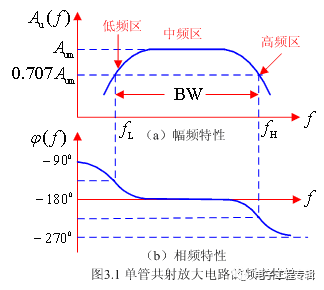
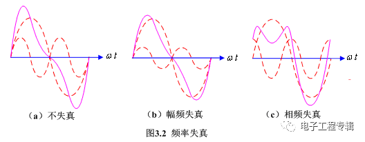
Representation of frequency response → give the frequency characteristics of the common-emitter circuit → qualitative analysis of its characteristics and causes, and introduce several concepts ( f L , f H , BW ) → frequency distortion. 3.1.1 Representation of frequency response A ̇ u (f)= A u (f)∠φ(f) A u (f) - amplitude-frequency characteristics φ(f) - phase frequency characteristics The amplitude-frequency characteristics and phase-frequency characteristics of a typical single-tube common-emitter amplifier circuit are shown in Figure 3.1. It can be known from the amplitude-frequency characteristics that in the low frequency band, as the frequency f decreases, the amplification factor decreases; in the high frequency band, as the frequency f increases, the amplification factor decreases. Causes: In the low frequency band, as the frequency f decreases, the capacitive reactance of the coupling capacitor increases → its voltage dividing effect increases → the voltage actually applied to the input terminal of the amplifying circuit decreases → the output voltage drops → the amplification factor decreases. In the high frequency band, as the frequency f increases, the capacitive reactance of the triode inter-electrode capacitance decreases → its shunting effect increases → the actual amplified current decreases → the amplification factor decreases. It can be known from the phase-frequency characteristics that the low frequency band will generate an additional phase shift of Δφ from 0° to 90° compared with the middle frequency band; the high frequency band will produce an additional phase shift Δφ of 0° to -90° lag compared with the middle frequency band. 3.1.2 Lower limit frequency, upper limit frequency and pass band f L — lower limit frequency f H — upper limit frequency BW - passband, where BW = f H - f L The passband characterizes the responsiveness of the amplifying circuit to different frequency input signals. The larger the value, the stronger the responsiveness to the input signals of different frequencies. It is one of the important technical indicators of the amplifier circuit. 3.1.3 Frequency Distortion Due to the limitation of the passband BW, the amplification circuit has different amplification factors and phase shifts for different frequencies. Therefore, when the input signal contains multiple harmonics, the output waveform will be distorted, called frequency distortion. Frequency distortion includes amplitude-frequency distortion and phase-frequency distortion. Amplitude-frequency distortion: Distortion caused by the amplification circuit's different amplification factors for input signals of different frequencies. Phase-frequency distortion: The distortion caused by the phase shift of the input signal of different frequencies to the amplifying circuit. For example, suppose that the input signal contains two sinusoidal quantities of frequency f 1 and f 2 , as shown in Figure 3.2(a), if the amplifier circuit equally amplifies the signals of the two frequencies, and the phase shift is also the same, Obtain the undistorted output waveform shown in Figure 3.2(a); if the amplification circuit reduces the amplification factor of the signal with frequency f 2 , as shown in Figure 3.2(b), the distortion waveform shown in Figure 3.2(b) is obtained. This distortion is amplitude-frequency distortion; if the amplifier circuit produces different additional phase shifts for the signals of frequencies f 1 and f 2 , as shown in Figure 3.2(c), the distortion waveform shown in Figure 3.2(c) is obtained. This distortion is phase frequency distortion. 5V 3A Usb Charger,5V3A Wall Charger,5V3A Usb Wall Charger,5V 3A Usb Output Charger Guangdong Mingxin Power Technologies Co.,Ltd. , https://www.mxpowersupply.com

