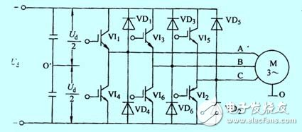
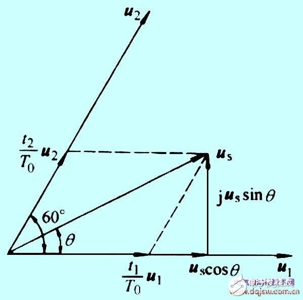
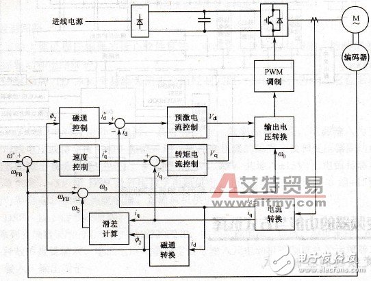
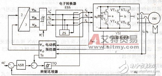
The frequency converter is a device that converts a commercial power supply (50 Hz or 60 Hz) into an AC power supply of various frequencies to realize variable speed operation of the motor, wherein the control circuit completes control of the main circuit, and the rectifier circuit converts the alternating current into direct current, and the middle of the direct current The circuit smoothes the output of the rectifier circuit, and the inverter circuit reverses the direct current into alternating current. For a frequency converter such as a vector control inverter that requires a large amount of calculations, sometimes a CPU for torque calculation and some corresponding circuits are required. The frequency conversion speed regulation achieves the purpose of speed regulation by changing the frequency of the power supply of the stator winding of the motor. The direct function of the inverter: 1. By changing the voltage and frequency of the motor, the speed of the motor can be adjusted infinitely. 2, soft start energy saving, power factor compensation energy saving. Indirect role of the inverter: 1. Energy saving (power saving). Fans, pumps and other equipment traditional speed control method is to adjust the air volume and water supply by adjusting the baffle and valve opening of the inlet or outlet. The input power is large, and a large amount of energy is consumed in the interception process of the baffle and the valve. in. When using variable frequency speed regulation, if the flow demand is reduced, the speed of the pump or fan can be reduced to meet the requirements and reduce power consumption. 2. Improve the automation of production equipment. There are currently many brands of inverters. The main circuit is a power conversion part that supplies a voltage-regulating and frequency-modulated power supply to the asynchronous motor. The main circuit of the frequency converter can be roughly divided into two types: the voltage type is a frequency converter that converts the direct current of the voltage source into an alternating current, and the filtering of the direct current circuit is a capacitor. . The current type is a frequency converter that converts the direct current of the current source into an alternating current, and the direct current loop filtering is an inductance. It consists of three parts: a "rectifier" that converts the power frequency power supply into DC power, a "flat wave loop" that absorbs the voltage ripple generated by the converter and the inverter, and a "reverse" that converts the DC power into AC power. Transformer." 1, the rectifier Recently used a large number of diode converters, which convert the commercial power supply into a DC power supply. Two sets of transistor converters can also be used to form the inverter, and the regenerative operation can be performed because the power direction is reversible. 2, flat wave circuit The DC voltage rectified by the rectifier contains a ripple voltage of 6 times the frequency of the power supply, and the ripple current generated by the inverter also causes the DC voltage to fluctuate. In order to suppress voltage fluctuations, the ripple voltage (current) is absorbed by the inductor and the capacitor. When the device capacity is small, if the power supply and the main circuit constitute a device with a margin, the inductor can be omitted and a simple smoothing circuit can be used. 3. Inverter In contrast to the rectifier, the inverter converts the DC power to the AC power of the required frequency, and the three switching devices are turned on and off at the determined time to obtain the 3-phase AC output. The switching time and voltage waveforms are shown by taking a voltage type pwm inverter as an example. The inverter control circuit is a circuit that provides control signals to the main circuit of the asynchronous motor (voltage and frequency adjustable). It has an "arithmetic circuit" of frequency and voltage, a "voltage and current detecting circuit" of the main circuit, and a motor " The speed detecting circuit is composed of a "driving circuit" that amplifies a control signal of the arithmetic circuit, and a "protective circuit" of the inverter and the motor. (1) Operation circuit: The external speed and torque commands are compared with the current and voltage signals of the detection circuit to determine the output voltage and frequency of the inverter. (2) Voltage and current detection circuit : It is isolated from the main circuit potential to detect voltage and current. (3) Drive circuit: A circuit that drives the main circuit device. It is isolated from the control circuit to turn the main circuit device on and off. (4) Speed ​​detection circuit: The signal of the speed detector (tg, plg, etc.) mounted on the asynchronous motor shaft machine is sent to the calculation circuit as a speed signal, and the motor can be operated at the command speed according to the command and calculation. (5) Protection circuit: Detect the voltage, current, etc. of the main circuit. When an abnormality such as overload or overvoltage occurs, in order to prevent damage to the inverter and the asynchronous motor, the inverter is stopped or the voltage and current values ​​are suppressed. The low-voltage universal variable frequency output voltage is 380 ~ 650V, the output power is 0.75 ~ 400kW, the working frequency is 0 ~ 400Hz, and its main circuit uses AC-DC-AC circuit. The way it is controlled has gone through the following four generations. 1, sinusoidal pulse width modulation (SPWM) control method The utility model has the advantages that the control circuit has the advantages of simple structure, low cost, good mechanical property hardness, and can meet the requirements of the smooth speed regulation of the general transmission, and has been widely used in various fields of the industry. However, in this mode of control, at low frequencies, the torque is affected by the voltage drop of the stator resistance due to the lower output voltage, which reduces the maximum output torque. In addition, its mechanical characteristics do not have DC motor hard, dynamic torque capability and static speed regulation performance are not satisfactory, and the system performance is not high, the control curve will change with the load change, the torque response is slow, the motor turns The moment utilization rate is not high, and the performance is degraded due to the existence of the stator resistance and the dead zone effect of the inverter at a low speed, and the stability is deteriorated. Therefore, people have also studied vector control frequency control. 2. Voltage space vector (SVPWM) control mode It is based on the premise of the three-phase waveform overall generation effect, and aims to approximate the ideal circular rotating magnetic field trajectory of the motor air gap, and generates a three-phase modulation waveform at a time, and controls the inscribed polygon to approach the circle. After practice, it has been improved, that is, the introduction of frequency compensation can eliminate the error of speed control; estimate the magnitude of the flux linkage through feedback to eliminate the influence of stator resistance at low speed; close the output voltage and current to improve the dynamic accuracy and stability. However, there are many control circuit links and no torque adjustment is introduced, so the system performance has not been fundamentally improved. 3. Vector control (VC) mode The vector control frequency conversion speed regulation method is to convert the stator currents Ia, Ib, Ic of the asynchronous motor in the three-phase coordinate system through the three-phase-two-phase transformation, and equivalent to the alternating current Ia1Ib1 in the two-phase stationary coordinate system, and then pass According to the rotor field oriented rotation transformation, equivalent to the DC current Im1, It1 in the synchronous rotating coordinate system (Im1 is equivalent to the excitation current of the DC motor; It1 is equivalent to the armature current proportional to the torque), and then imitates the DC motor The control method obtains the control amount of the DC motor, and realizes the control of the asynchronous motor through the inverse transformation of the corresponding coordinates. The essence is that the AC motor is equivalent to a DC motor, and the two components of speed and magnetic field are independently controlled. By controlling the rotor flux linkage and then decomposing the stator current to obtain two components of torque and magnetic field, coordinate transformation is used to realize orthogonal or decoupling control. The proposed vector control method has epoch-making significance. However, in practical applications, because the rotor flux linkage is difficult to accurately observe, the system characteristics are greatly affected by the motor parameters, and the vector rotation transformation used in the equivalent DC motor control process is complicated, making the actual control effect difficult to achieve the ideal analysis. result. 4, direct torque control (DTC) mode In 1985, Professor DePenbrock of Ruhr University in Germany first proposed the direct torque control frequency conversion technology. This technology largely solves the above-mentioned shortcomings of vector control, and has been rapidly developed with novel control ideas, simple and clear system structure, and excellent dynamic and static performance. At present, this technology has been successfully applied to high-power AC drives for electric locomotive traction. The direct torque control directly analyzes the mathematical model of the AC motor in the stator coordinate system to control the flux linkage and torque of the motor. It does not require the AC motor to be equivalent to a DC motor, thus eliminating many of the complex calculations in vector rotation transformation; it does not require the control of a DC motor, nor does it need to simplify the mathematical model of the AC motor for decoupling. 5, matrix type AC-AC control method VVVF frequency conversion, vector control frequency conversion, direct torque control frequency conversion are all one of AC-DC-AC frequency conversion. The common disadvantage is that the input power factor is low, the harmonic current is large, the DC circuit needs a large storage capacitor, and the regenerative energy cannot be fed back to the grid, that is, the four-quadrant operation cannot be performed. To this end, matrix-type AC-AC frequency conversion came into being. Since the matrix type AC-AC frequency conversion eliminates the intermediate DC link, the bulky and expensive electrolytic capacitor is omitted. It can achieve a power factor of l, the input current is sinusoidal and can operate in four quadrants, and the system has a high power density. Although the technology is not yet mature, it still attracts many scholars to study in depth. The essence is not to indirectly control the current, flux linkage, etc., but to achieve the torque directly as the controlled amount. The specific method is: 1) Control the stator flux linkage to introduce the stator flux linkage observer to realize the speed sensorless mode; 2) Automatic identification (ID) relies on accurate motor mathematical model to automatically identify motor parameters; 3) Calculate the actual value, calculate the actual torque, stator flux and rotor speed in real time according to the stator impedance, mutual inductance, magnetic saturation factor, inertia, etc.; 4) Realize the Band-Band control. The Band-Band control of the flux linkage and torque generates a PWM signal to control the inverter switching state. Matrix AC-AC has fast torque response ("2ms"), high speed accuracy (±2%, no PG feedback), high torque accuracy ("+3%"; also has a high start-up turn Moment and high torque accuracy, especially at low speeds (including 0 speed), can output 150% to 200% torque.
We are professional manufacturer of various kinds of casters .The most professional production, the most safe and durable caster is that we adhere to the concept of High Quality and Mutual Benefit
With casters production enterprises of since its inception, specializing in the production of industrial casters, scaffolding caster for 20 years. In the past 20 years, we have rich experience in design and production standards, won a good reputation at home and abroad. With casters to customers in North America, Europe, Asia, Australia, South Africa and the Middle East, we experience also let us understand the needs of the international market, fast delivery and safe use. The company has 150 units/sets of production equipment, 2 pouring PU production line, 2 rubber vulcanization production line , 10 sets of large-scale injection molding equipment, automatic welding equipment, equipped with professional level of production to modernize. Using the fully and semi-automatic machinery to achieve excellence in technology and the production of consistency; Research and development team using advanced CAD/CAM software and three-dimensional software design OEM caster; Equipped with professional mold development workshop, by professional engineers to adjust the existing model, constantly updated design, so as to adapt to the changing demands of customers at home and abroad; By professional personnel in accordance with the strict product inspection standards for all products are factory inspection, to ensure the high quality of the products.
We produce PU casters and rubber casters, high bearing capacity, the use of lightweight flexible, but won't hurt smooth floor .Special process increases the stability and the security of the load, the high quality raw materials and advanced processing technology, ensure with casters do not come unglued, no crack, more wear-resisting ;Processing with galvanized metal stents or plastic spraying Metal , make the caster wheel bracket is not easy to rust.
Light Duty Casters,Lower Gravity Casters,Medium Heavy Casters,Industrial Casters,Extra Heavy Duty Casters,Shock Absorb Casters,Mute Casters BAODING JIMAOTONG IMPORT AND EXPORT CO., LTD , https://www.chinagroundscrew.com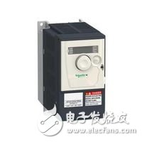
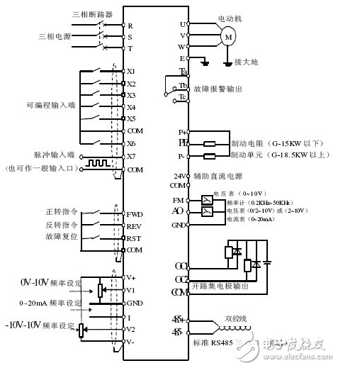
Inverter wiring diagram 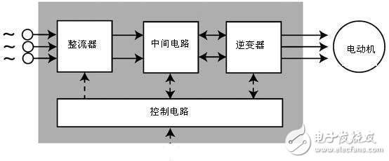
Frequency converter structure and work flow chart 