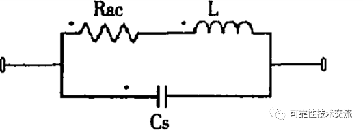
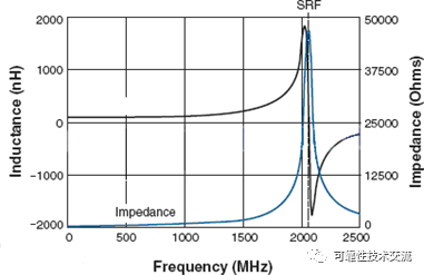
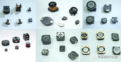
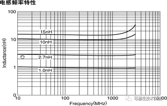
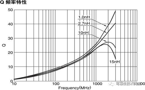
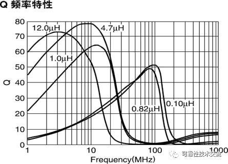
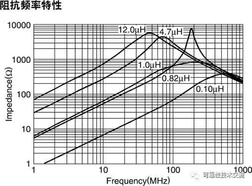
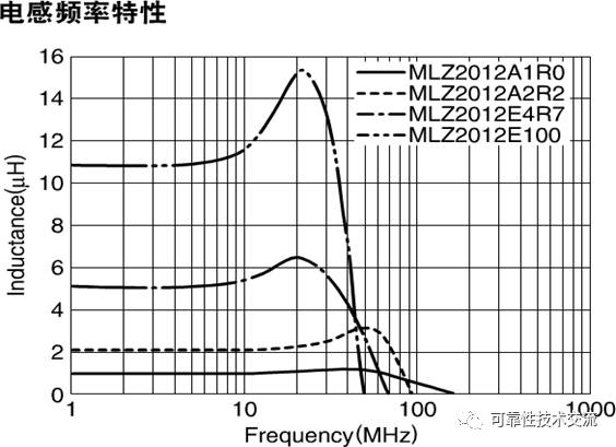
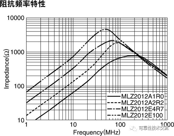
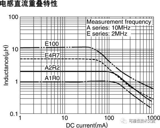
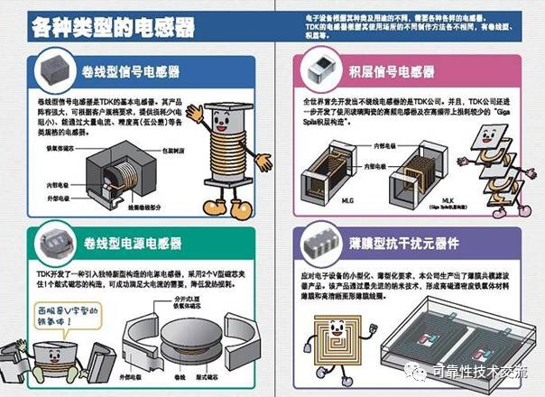
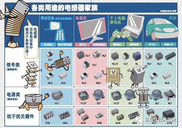
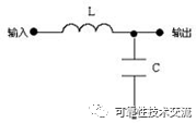
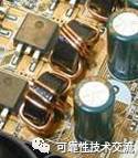
Components that can generate inductance are collectively referred to as inductors and are often referred to simply as inductors. Inductance is an electromagnetic induction component that is wound with insulated wires (such as enameled wire, sandbag wire, etc.) and is a common component. The role of the inductor: through the DC resistance AC is a simple statement, the AC signal is isolated, filtered or combined with capacitors, resistors, etc. to form a resonant circuit. It uses the principle of electromagnetic induction to work. In an AC circuit, the inductor has the ability to block the passage of AC, but it does not work for DC (except for the DC resistance of the coil itself). Therefore, the inductor coil can be used for blocking, step-down, cross-linking, and load in the AC circuit. When the inductor and capacitor are matched, it can be used for tuning, filtering, frequency selection, decoupling, etc. The inductor coil is one of the basic components that make up the circuit. Since the inductance was discovered by foreign scientist Henry, the unit of inductance is "Henry" Inductance symbol: L Inductance units: Hen (H), millihenry (mH), micro-henry (uH), their conversion relationship is 1H = 1000mH = 1000 000uH. The type of the inductive component generally consists of the following four parts: The first part: the main name, expressed in letters. Where L represents the inductor and ZL represents the choke. Part II: Features, represented by letters, where G stands for high frequency. Part III: Type, expressed in letters, where X stands for small size. The fourth part: the difference code, represented by numbers or letters. For example: The LGX type is a small high frequency inductor. It should be noted that the current model naming methods for fixed inductors vary from manufacturer to manufacturer and there is no uniform standard. (I) Structure and Characteristics of Inductors Inductors are generally composed of a skeleton, a winding, a shield, a packaging material, a core or a core. 1. The skeleton skeleton refers to the bracket that winds the coil. Some large fixed inductors or adjustable inductors (such as oscillating coils, chokes, etc.), most of which are wrapped around the enamel wire (or yarn wrapped wire), then the core or copper core, iron core, etc. Load the inner cavity of the skeleton to increase its inductance. The skeleton is usually made of plastic, bakelite or ceramic, and can be made into different shapes according to actual needs. Small inductors (such as color code inductors) generally do not use a skeleton, but directly wrap the enamel wire around the core. Hollow inductors (also known as tire coils or air-core coils, mostly used in high-frequency circuits) do not use cores, skeletons, and shields. Instead, they are wound on the mold and then removed from the mold. Open a certain distance. 2. Winding windings are a group of coils with defined functions that are an essential part of an inductor. The windings are divided into single layers and multiple layers. The single-layer winding has two kinds of windings (one turn of the wire once in the winding process) and the middle winding (a certain distance between each turn of the winding); the multilayer winding has layered flat winding and chaos Winding, honeycomb type winding and so on. 3. Cores and magnetic rod cores and magnetic rods are generally made of nickel-zinc ferrite (NX series) or manganese-zinc ferrite (MX series). They have a "work" shape, a column shape, a hat shape, and an "E" shape. A variety of shapes such as cans. 4. The iron core material mainly includes silicon steel sheet, permalloy, etc., and its shape is mostly "E" type. 5. The shield is added to the metal screen cover (such as the oscillation coil of the semiconductor radio, etc.) in order to prevent the magnetic field generated by some inductors from affecting the normal operation of other circuits and components. Inductors with shields increase the loss of the coil and lower the Q. 6. After some inductors (such as color code inductors, color ring inductors, etc.) are wound, the coils and cores are sealed with a packaging material. The packaging material is made of plastic or epoxy resin. (2) Small fixed inductors Small fixed inductors are usually wound directly on the core by enameled wires. They are mainly used in circuits such as filtering, oscillation, notching, and delay. They are available in both hermetic and non-sealed packages. Form, both forms have both vertical and horizontal shape structure. 1. Vertical sealed fixed inductors Vertical sealed fixed inductors use the same-direction pins. There are series of inductors such as LG and LG2. The inductance range is 0.1~2200μH (straight on the housing), and the rated working current is 0.05. ~1.6A, the error range is ±5%~±10%. Imported TDK series color code inductors, the inductance of which is marked on the surface of the inductor with color points. 2. Horizontal sealed fixed inductors Horizontal sealed fixed inductors adopt axial type pins, and domestically produced series of LG1, LGA, LGX, etc. The inductance of the LG1 series inductors ranges from 0.1 to 22000μH (straight to the housing), the rated operating current is 0.05~1.6A, and the error range is ±5%~±10%. The LGA series inductors are ultra-small and similar in appearance to 1/2W color ring resistors. The inductance ranges from 0.22 to 100μH (marked on the housing with a color ring) and the rated current is 0.09~0.4A. For example, LGX series color code inductors are also small package structure, the inductance range is 0.1~10000μH, and the passenger current is divided into four specifications: 50mA, 150mA, 300mA and 1.6A. (3) Adjustable inductors commonly used in adjustable inductors include oscillating coils for semiconductor radios, row oscillating coils for televisions, linear coils for winding lines, idling coils for intermediate frequency, frequency compensation coils for acoustics, and wave-blocking coils. 1. Straight standard method: On the outer casing of the inductor coil, the main parameters such as the inductance of the inductor, the allowable error and the maximum operating current are directly indicated by numbers and characters. 2. Color standard method: same resistance method. The unit is μH 3, inductance symbol 1. Nominal inductance: The size of the inductance indicated above indicates the inherent characteristics of the coil itself, mainly depending on the number of turns of the coil, the structure and the winding method, etc., regardless of the current magnitude, reflecting the ability of the inductor to store magnetic field energy, and also reflecting the change of current through the inductor. The ability to generate an induced electromotive force. The unit is Hen (H). 2. Allowable error: The maximum allowable deviation range of the actual inductance of the inductor relative to the nominal value is called the allowable error. 3. Inductive reactance XL: The magnitude of the inductance coil's resistance to AC current is called Sense XL, and the unit is ohm. Its relationship with the inductance L and the AC frequency f is XL=2πfL. 4 quality factor Q: A physical quantity representing the mass of the coil, Q is the ratio of the inductive reactance XL to its equivalent resistance, ie: Q = XL / R. The higher the Q value of the coil, the smaller the loss of the loop. The Q value of the coil and the DC resistance of the wire The dielectric loss of the skeleton, the loss caused by the shield or the iron core, and the influence of the high-frequency skin effect. The Q value of the coil is usually tens to 100. 5. Rated current: The rated current refers to the working current that can ensure the normal operation of the circuit. 6. Nominal voltage 7. Distributed capacitance (parasitic capacitance) The capacitance between the turns and turns of the coil, between the coil and the shield, and between the coil and the master is called a distributed capacitance. The presence of distributed capacitance makes the coil The Q value decreases and the stability deteriorates, so the smaller the distributed capacitance of the coil, the better. The segmented winding method reduces the distributed capacitance. 8, self-resonant frequency (Q maximum is the frequency) When the frequency is high, the inductance is no longer treated as a lumped parameter, and the influence of parasitic parameters cannot be ignored. Parasitic parameters include Rac equivalent series resistance (ESR) and Cs equivalent shunt inductance (ESL). The actual equivalent circuit of the inductor is shown in the figure. Inductance, inductance, and frequency are taken as an example of a 100nH wirewound inductor, as shown in the following figure: As can be seen from the above figure: 1. When the frequency is lower than the self-resonant frequency (SRF), the inductance inductance increases with increasing frequency; 2. When the frequency is equal to the self-resonant frequency (SRF), the inductance inductance reaches the maximum value; 3. When the frequency is higher than the self-resonant frequency (SRF), the inductance inductance decreases with increasing frequency; (1) Classification of inductance According to the shape, the inductor can be divided into a hollow inductor (air core coil) and a solid inductor (solid coil). According to the nature of the work, the inductor can be divided into high-frequency signal inductors (various antenna coils, oscillating coils), general signal inductors (various chokes, filter coils, etc.) and power inductors. According to the package form, the inductor can be divided into a common inductor, a color ring inductor, an epoxy inductor, a chip inductor, and the like. According to the inductance, the inductor can be divided into a fixed inductor and a tunable inductor. (2) Selection of inductance 1. Inductance for high frequency signals Inductors for high frequency signals are mainly used on RF signals. (1) Main parameters: Inductance range: 0.6-390nH; DC resistance: There are a variety of DC resistances to choose from. Generally speaking, the larger the inductance value, the larger the corresponding DC resistance. Self-resonant frequency: up to 12GHz. The larger the inductance value, the smaller the corresponding self-resonant frequency. Rated current: tens of milliamps to hundreds of milliamps. The larger the inductance value, the smaller the corresponding rated current tends to be. (2) Application characteristics: The relationship between the inductance value and the self-resonance point and the operating frequency is shown in the following figure (taking TDK inductor as an example): It can be seen from the above figure that the inductance value is basically stable when the operating frequency is lower than the resonant frequency; however, once the operating frequency exceeds the resonant frequency, the inductance value will increase rapidly, but if the frequency continues to increase to a certain frequency, the inductance The value will decrease rapidly (this process of reduction is not reflected in the above figure). In applications, an inductor with a resonant frequency above the operating frequency should be selected. For high-frequency signal inductors, the resonant frequency point is generally above 1 GHz, so this type of inductor can support a very high operating frequency. 2. General signal inductor General signal inductors are mainly used on high speed signals. (1) Main parameters: Inductance range: 0.01-1000uH; DC resistance: There are a variety of DC resistors to choose from. Generally speaking, the larger the inductance value, the larger the DC resistance. Generally, the signal has a DC resistance value that is larger than the inductance of the high-frequency signal and the inductance of the power supply, and ranges from 100 milliohms to several ohms; Self-resonant frequency: tens of MHz to several hundred MHz. The larger the inductance value, the smaller the corresponding self-resonant frequency. Rated current: a few milliamps to tens of milliamps. The larger the inductance value, the smaller the corresponding rated current tends to be. (2) Application characteristics: The relationship between the Q value of the inductor and the impedance and the operating frequency is shown in the figure below (taking TDK inductor as an example): From the impedance frequency characteristic curve above, it can be seen that when the operating frequency is lower than the resonant frequency, the inductance of the inductor exhibits inductivity, and the impedance increases with increasing frequency; but once the operating frequency exceeds the resonant frequency, the inductance will exhibit capacitiveity. The impedance decreases as the frequency increases. Similarly, when the operating frequency is less than the resonant frequency, the inductance value remains basically stable; but once the operating frequency exceeds the resonant frequency, the inductance value will increase rapidly. If the frequency continues to increase to a certain frequency, the inductance value will be rapidly reduced. Small (general signal inductance frequency characteristic curve is similar to high frequency inductance characteristic curve, not given here). In applications, an inductor with a resonant frequency above the operating frequency should be selected. For general signal inductors, the resonant frequency is typically within a few hundred MHz. This type of inductor is also the most commonly used inductor in high speed circuit design. In the high-speed design, the board interconnect signal, the ripple is larger than the signal in the board, and can be filtered by using this type of inductor. In the design, it is necessary to pay attention to the high-frequency signal inductor and the general signal inductor rated current are relatively small, and the DC resistance is relatively large, it is not recommended for power supply filtering. 3. Power supply inductance The inductor for the power supply is mainly used in the power supply circuit. (1) Main parameters: Inductance range: 1-470uH; DC resistance: There are a variety of DC resistances to choose from. Generally speaking, the larger the inductance value, the larger the corresponding DC resistance, ranging from a few milliohms to a few ohms; Self-resonant frequency: tens of MHz to several hundred MHz. The larger the inductance value, the smaller the corresponding self-resonant frequency. Rated current: a few milliamps to tens of milliamps. The larger the inductance value, the smaller the corresponding rated current. (2) Application characteristics: The relationship between inductance value and impedance and operating frequency and the DC characteristic curve of the inductor are shown in the following figure (taking TDK inductor as an example): From the inductance frequency characteristic curve, when the operating frequency is less than the resonant frequency, the inductance value basically remains stable; but once the operating frequency exceeds the resonant frequency, the inductance value will increase rapidly. If the frequency continues to increase to a certain frequency, the inductance The value will decrease rapidly. In applications, an inductor with a resonant frequency above the operating frequency should be selected. For power supply inductors, the resonant frequency is typically in the tens of MHz. This type of inductor is also the most commonly used inductor for power supply filtering in high speed circuit designs. It can be seen from the impedance frequency characteristic curve that the inductor inductance exhibits inductivity and the impedance increases with increasing frequency when the operating frequency is lower than the resonant frequency. However, once the operating frequency exceeds the resonant frequency, the inductor will exhibit capacitive and impedance. Decreased as the frequency increases. It can be seen from the DC characteristic curve of the inductor that when used for power supply filtering, the operating current of the inductor must be less than the rated current. If the operating current is greater than the rated current, the inductance may not be damaged, but the inductance value may be lower than the nominal value. At the same time, the voltage drop caused by its DC resistance can be considered. 1. The power inductor package is packaged in the size of the skeleton. The ellipsoidal representation of the patch, such as 5.8(5.2)×4, represents an inductor with a long diameter of 5.8 mm and a short diameter of 5.2 mm and a height of 4 mm. The plug-in uses a cylindrical representation such as φ6×8 to represent an inductor with a diameter of 6 mm and a height of 8 mm. Only their skeletons are generally versatile, or they must be made. 2. The general linear inductor, the color ring inductor and the resistor and capacitor package have the same representation. The size of the patch is expressed as 0603, 0805, 0402, 1206, and the like. Plug-in power is expressed as 1/8W, 1/4W, 1/2W, 1W, etc. 3. Color ring inductance Inductance: 0.1uH ~ 22MH Size: 0204, 0307, ​​0410, 0512 Bean-shaped inductor: 0.1uH ~ 22MH Size: 0405, 0606, 0607, 0909, 0910 Accuracy: J=±5% K=±10% M=±20% Accuracy: J=±5% K=±10% M=±20% The color ring inductance reading method of the plug-in: the same color ring resistance 4. Vertical inductor Inductance: 0.1uH ~ 3MH Specifications: PK0455/PK0608/PK0810/PK0912 5. Axial filter inductor Specifications: LGC0410/LGC0513/LGC0616/LGC1019 Inductance: 0.1uH-10mH. Rated current: 65mA~10A. The Q value is high, the price is generally low, and the self-resonance frequency is high. 6. Magnetic ring inductance Specifications: TC3026/TC3726/TC4426/TC5026 Dimensions (in mm): 3.25~15.88 7. Air core inductance In order to obtain a large inductance value, the air core inductor is often wound with more enameled wires, and in order to reduce the influence of the line resistance of the inductor itself on the direct current, an enameled wire having a relatively large wire diameter is used. However, in some products with a small volume, it is not realistic to use a very large air core inductor, which not only increases the cost, but also limits the volume of the product. In order to increase the inductance value and maintain a light weight, we can insert a core and a core into the air core inductor to improve the self-inductance of the inductor, thereby increasing the inductance value. At present, most of the computers are magnetic core inductors. Basic role: filtering, oscillation, delay, notch, etc. Image said: "through DC, blocking communication" Detailed explanation: In the electronic circuit, the inductor coil acts on the AC finite current, and it can form a high-pass or low-pass filter, a phase shift circuit and a resonant circuit with a resistor or a capacitor; the transformer can be AC-coupled, transformed, and changed. Flow and impedance transformations, etc. It is known from the inductive reactance XL=2πfL that the larger the inductance L is, the higher the frequency f is, and the larger the inductive reactance is. The voltage across the inductor is proportional to the inductance L and proportional to the current change rate Δi/Δt. This relationship can also be expressed by The inductor coil is also an energy storage component that stores energy in the form of magnets. The amount of stored energy can be expressed as: WL = 1/2Li2. It can be seen that the larger the inductance of the coil, the larger the flow, and the more energy is stored. The most common role of the inductor in the circuit is to form an LC filter circuit with the capacitor. We already know that the capacitor has the ability to "block DC, pass AC", while the inductor has the function of "DC, DC". If the DC current with many interfering signals is passed through the LC filter circuit (as shown in the figure), then the AC interference signal will be consumed by the capacitor into thermal energy; when the relatively pure DC current passes through the inductor, the AC interference signal is also It becomes magnetic and thermal, and the higher frequency is most easily affected by the inductance, which can suppress the interference signal of higher frequency. LC filter circuit The inductance in the power supply section of the board is generally surrounded by a thin core with a very large wire diameter on a circular core coated with various colors. Moreover, there are generally several large filter aluminum electrolytic capacitors in the vicinity, which are composed of the above LC filter circuit. In addition, the circuit board also uses a large number of "snake line + patch tantalum capacitors" to form an LC circuit, because the snake line is folded back and forth on the board, it can also be regarded as a small inductor. Magnetic device derating standard Description: 1. For network transformers, the derating requirements are usually met, so derating is not considered; 2. Magnetic devices include magnetic beads. 1. Where the inductor is used Wet and dry, the temperature of the environment, high-frequency or low-frequency environment, the inductance should be expressed inductive, or impedance characteristics, etc., should pay attention. 2, the frequency characteristics of the inductor At low frequencies, the inductor generally exhibits an inductive characteristic, which only functions to store energy and filter high frequencies. However, at high frequencies, its impedance characteristics are very obvious. There are energy consumption and heat, and the inductive effect is reduced. The high frequency characteristics of different inductors are different. The following explains the inductance of the ferrite material: The ferrite material is a ferro-magnesium alloy or an iron-nickel alloy. This material has a high magnetic permeability, and it can be the smallest capacitance generated by the high-frequency high-resistance between the coil windings of the inductor. Ferrite materials are often used at high frequencies because their main inductance characteristics at low frequencies make the losses on the line small. At high frequencies, they mainly exhibit a reactance characteristic ratio and change with frequency. In practical applications, ferrite materials are used as high frequency attenuators for RF circuits. In fact, the ferrite is preferably equivalent to the parallel connection of the resistor and the inductor. The resistor at the low frequency is short-circuited by the inductor, and the impedance of the inductor at a high frequency becomes so high that the current passes through the resistor. Ferrite is a consuming device in which high-frequency energy is converted into thermal energy, which is determined by its electrical resistance characteristics. 3, the maximum current that the inductor design must withstand, and the corresponding heat. 4. When using the magnetic ring, compare the magnetic ring part above to find the corresponding L value, corresponding to the scope of use of the material. 5, pay attention to the wire (enamel wire, yarn package or bare wire), commonly used enameled wire. To find the most suitable line.
The JUK universal Screw Terminal Block series has the typical features which are decisive for practical applications:
l The universal foot allows the terminal blocks to be easily snapped onto the NS35 or NS32 DIN Rail with G shape.
l Closed screw guide holes ensure screwdriver operation perfect.
l For terminal block with different wire cross-sectional areas, complete accessories are available, such as end plates, partition plates, etc.
l Potential distribution achieved by fixed bridges in the terminal center or insertion bridges in the clamping space.
l Same shape and pitch Grounding Terminal Blocks as the JUK universal series.
l Adopt ZB marker strip system,achieve unified identification.
Electric Screw Terminal,Screw Type Terminal Blocks,Screw Type Terminal Blocks Din Rail,Nylon Screw Terminal Block Wonke Electric CO.,Ltd. , https://www.wkdq-electric.com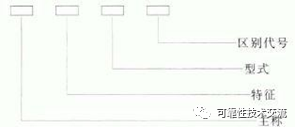



Types of Hot spot temperature drop DC current derating Surge current derating Surge voltage derating transformer Tmax-25°C N/A 90% 90% inductance Tmax-25°C 90% 90% 90%