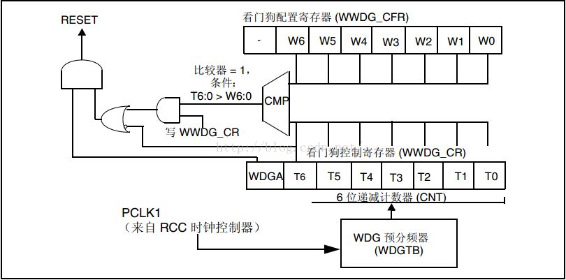
Independent watchdog (iwdg) 1 Introduction: It is used to detect and resolve faults caused by software errors, and a system reset is generated when the counter reaches the set timeout value. Its characteristics are as follows: 1. The clock used is generated by a separate RC oscillator, so it can operate in standby and stop modes. 2. After the watchdog is activated, a system reset will occur if the value of the down counter reaches 0X000. Function brief: The independent watchdog is started by writing 0XCCCC to the key register (IWDG_KR). The counter will count down from the reset value 0XFFF. When the value of the counter reaches 0X000, a reset signal is generated. When the count value has not reached 0X000, 0XAAAA is written to the IWDG_KR register, and the value of the IWDG_RLR register is reloaded to the timer, thereby avoiding a reset (commonly known as feeding the dog). It can be seen that when the software runs out of problems, when the function of feeding the dog cannot be performed within a certain period of time, a system reset will be generated to realize the detection and resolution of the software failure. Related registers: 1, the keyword register: The valid bits of the key register are bits 0 through 15 and bits 16 through 31 are reserved. As explained earlier, by writing 0XAAAA to this register, the value in the IWDG_RLR register can be reloaded into the counter to avoid a system reset. Since IWDG_PR (prescaler register) and IWDG_RLR (reload register) are write-protected registers, writing a key value of 0X5555 in this register enables access to IWDG_PR and IWDG_RLR. 2. Prescaler register: The valid bits of this register are from bit 0 to bit 2, and other bits are reserved. By setting the value of PR[2:0], the corresponding division factor is set. 3. Reload register: It has been mentioned above that the value in this register will be reloaded into the counter, and the counter will count down from this value, which shows that the value in this register and the value in the prescaler register together determine the timeout period. 4, the status register: In this register, only bit 0 and bit 1 are valid. Bit 0 (RVU) is the value update flag of the prescaler register. Bit 1 (PVU) is the counter reload value update flag. Related code analysis: The configuration of the independent watchdog through the relevant library functions is relatively simple, and the initialization process is as follows: IWDG_WriteAccessCmd(IWDG_WriteAccess_Enable); //Enable write to IWDG->PR IWDG->RLR IWDG_SetPrescaler(prer); //Set the IWDG division factor IWDG_SetReload(rlr); //Set the IWDG load value IWDG_ReloadCounter(); //reload (feeding the dog) IWDG_Enable(); //Enable the watchdog Introduction: In contrast to the independent watchdog, the so-called window watchdog sets a window value (upper and lower limits). A reset is generated when the down counter value is less than 0X40 (the window lower limit). Reloading the counter below the set window also performs a reset. The window watchdog can set the early wake-up interrupt. When the down counter is equal to 0X40, the interrupt will be triggered, and the dog and other related operations can be performed in the interrupt. block diagram: The block diagram of the window watchdog is as follows: The comparison of the block diagram to see the related introduction below! work process: The watchdog is enabled by setting the WDGA bit in the WWDG_CR register. The down counter is the lower 7 bits of the control register, which is reset when the 7th bit (ie, T6) is changed from 1 to 0 (ie, decremented from 0X40 to 0X3F). The lower 7 bits of the configuration register store the watchdog upper limit value. The value in the counter is compared with the upper limit value. If the dog is fed above the upper limit value, the reset will also be performed. This is also the window watchdog and the independent watchdog. The difference. It can be seen that the time for feeding the dog can only be between the upper limit and the lower limit, otherwise the reset operation will be performed. Related registers: 1. Control register (WWDG_CR): As described above, the valid bits are bits 0 to 7, bit 7 (WDGA) is the watchdog activation bit, and bit 0 to bit 6 are counters. 2. Configuration register (WWDG_CFR): The valid bits of this register are from bit 0 to bit 9. Bit 0 to bit 6 have been described above for storing the upper limit of the counter. Bits 7 and 8 are used to set the timer time base to select the corresponding clock divider. . Bit 9 is the early wake-up interrupt (EWI) introduced above. 3. Status register (WWDG_SR): The valid bit in this register has only bit 0, which is used to make the early wake-up interrupt flag (EWIF). 9V Dc Adapter,Interchangeable Plug 9V 1A Power Adapter,9V 1A Power Adapter,Ac Dc Adapter 9V 1A ShenZhen Yinghuiyuan Electronics Co.,Ltd , https://www.yhypoweradapter.com 3
3