Overview: 1 Qualcomm's Quick Charge 2.0 Hydrogen Water Generator Bottle,Hydrogen Rich Water Bottle,Hydrogen Rich Water Mug,Hydrogen Rich Water Generator Bottle Ningbo Multitasking Electronic Co.,Ltd , https://www.smartmultesic.com
In the past two years, the new generation of smartphones has become larger and larger, the resolution of screens is getting higher and higher, and the speed of mobile application processor (AP) is also getting faster and faster. These changes require larger capacity lithium batteries. To support.
As battery capacity increases, high-power and efficient fast charging technology becomes a must, and the existing traditional 5V USB charger uses the unified charging interface Micro-USB, according to the standards issued by the USB Association, the maximum allowable charging of Micro-USB The current is 1.8A, which means that the traditional 5V USB charger will be limited to 9W or less, and can no longer increase the output power.
In order to break through this technical bottleneck, MediaTek and Qualcomm, the world's largest mobile phone chip manufacturers, have introduced the function of fast charging in the new mobile phone chip solution. It takes about 2~3 hours to charge 100% of the charger in the past. Qualcomm and MediaTek's latest fast charging design, if combined with the modified charger, 50% charging takes only 20 minutes, 100% charging has the opportunity to drive down Within 90 minutes.
Although both Qualcomm and MediaTek have released their own fast charging solutions, their charging methods are very different. Let's introduce their charging principles and respond to the designed fast charger solution.
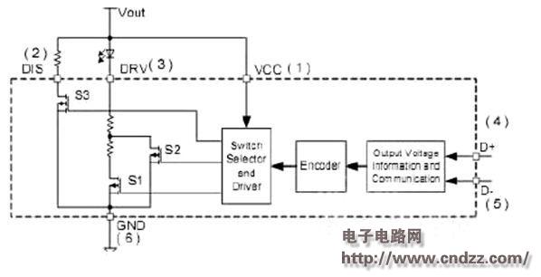
Qualcomm launched the Snapdragon 800 chip in 2013, which includes the QuickCharge 2.0 version of the platform. Its working principle is simply that the device outputs the voltage signal to the charger and charger through the USB data communication port D+/D-. Built-in USB input decoder chip to determine the charger needs output voltage. Although the fast charge output current is limited to less than 1.8A, the output voltage will be available in 5V, 9V and 12V options. The new QC2.0 standard fast charger is rated at 15W, which is 2~3 times higher than the conventional 5V USB charger.
Now introduce a fast charger developed with Qualcomm QC2.0 standard. The solution choice is the decoding chip iW620 developed by Dialog and the primary side PWM IC chip iW1760. 
The iW620 is a SOT-123 small package USB decoding IC. IC reads the required information from the USB data communication port D+/D-, and then outputs the signal from the DRV driver pin of the IC, giving the LED of the optocoupler different currents ( 2mA~10mA), corresponding to control different output voltages 5V /9V/12V, the signal is fed back to the primary power management chip iW1760 through the optocoupler.
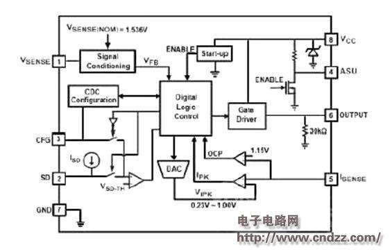
The iW1760 is a digitally controlled power management chip that implements the output voltage and current at the secondary side of the primary control. 
Inside the iW1760, there is a real-time waveform analyzer that reads the voltage waveform of the VSENSE pin in a cycle and then generates a feedback voltage VFB. This VFB signal can be accurately equivalent to the output voltage in most cases. Adjust the output voltage.
The VSENSE pin of the iW1760 has the function of reading the voltage sensing signal from the auxiliary winding of the power transformer and transmitting it to the internal digital control module of the IC for analysis to control the output voltage.
In this design, we use the LED of the optocoupler to receive the control signal from the secondary USB decoding IC iW620, and then feed the signal back to the primary side, drive and control the two sets of switches, and then control the two separately. The voltage dividing circuit formed by the voltage dividing resistor affects the signals of the three states of the input V sense, and the three states correspond to the three output voltages of 5V/9V/12V.
The current control of this line is achieved by controlling the IC Isense pin. The iW1760 senses the change in the secondary load current by detecting the primary side current, which is the source-to-ground current limiting resistor of the power switching MOSFET.
(Please read the PDF for details)