The 220V AC single-phase motor starting method is roughly divided into several types: the first type, the split-phase starting type, as shown in Figure 1, is assisted by the auxiliary starting winding, and its starting torque is not large. The operating rate remains approximately constant. Mainly used in electric fans, air conditioning fan motors, washing machines and other motors. Wiring diagram Secondly, when the motor is stationary, the centrifugal switch is turned on. After the power is supplied, the starting capacitor participates in the starting work. When the rotor speed reaches 70% to 80% of the rated value, the centrifugal switch will automatically jump off, and the starting capacitor completes the task. Was disconnected. The starting winding does not participate in the running operation, and the motor continues to operate in the running winding coil, as shown in Figure 2. Third, when the motor is stationary, the centrifugal switch is turned on. After the power is supplied, the starting capacitor participates in the starting work. When the rotor speed reaches 70% to 80% of the rated value, the centrifugal switch will automatically jump off, and the starting capacitor completes the task. Was disconnected. The running capacitor is connected to the start winding to participate in the operation. This connection is generally used in places where air compressors, cutting machines, woodworking machines, etc. are heavily loaded and unstable. Figure 3. 838 Electronics A motor with a centrifugal switch, if the motor cannot be started successfully in a short time, the winding coil will burn out quickly. Capacitance value: Double-valued capacitor motor, large starting capacitor capacity, small operating capacitor capacity, and withstand voltages are generally greater than 400V. Positive and negative control: Figure 4 is a wiring diagram with a positive and negative reverse switch. Generally, the starting winding of this motor has the same resistance value as the running winding, that is, the starting winding and the running winding of the motor are exactly the same in wire diameter and number of coils. This type of motor is generally used in washing machines. This method of forward and reverse control is simple and does not require complicated switching switches. Figure 1, Figure 2, Figure 3, Figure 5 forward and reverse control, just reverse the 1-2 line or 3-4 line. For the determination of the starting and running windings of Figure 1, Figure 2, Figure 3, the starting winding is usually much larger than the DC resistance of the running winding, which can be measured with a multimeter. Generally, the DC resistance of the winding is several ohms, and the DC resistance of the starting winding is ten ohms to several tens of ohms. In the future, we will continue to tell you the wiring diagram of the reverse switch. Figure 6 is the actual connection diagram between the switch and the motor. If the reverse switch is applied to the three-phase motor, there is no need to change it. For example, the single-phase motor is used for commutation, and the red, blue line is connected to the power supply. It is the starting winding coil lead-out line, the white line runs the winding coil lead-out line, and the left gray line is the rear-connected jumper. The forward-reverse switching is reversed by the cross-connecting piece of the switch. This kind of switch is insufficient. The point is that there is still a line that is not closed after the switch is turned off, so there is no guarantee in safety. Specialized Slip Ring,Slip Ring Rotary Joint,Slip Ring Induction Motor Rotor,Induction Motor Slip Ring Dongguan Oubaibo Technology Co., Ltd. , https://www.sliprob.com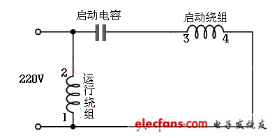
Figure 1 Capacitor running wiring circuit 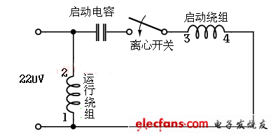
Figure 2 Capacitor start type wiring circuit 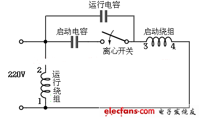
Figure 3 Capacitor start-up type wiring circuit (double-value capacitor) 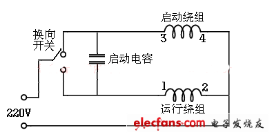
Figure 4 switch control positive and negative wiring 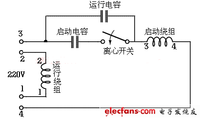
Figure 5 Double-value capacitor asynchronous motor reverse wiring diagram 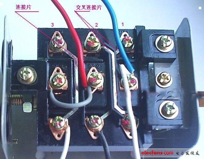
Figure 6 . Actual reverse switch and motor wiring diagram