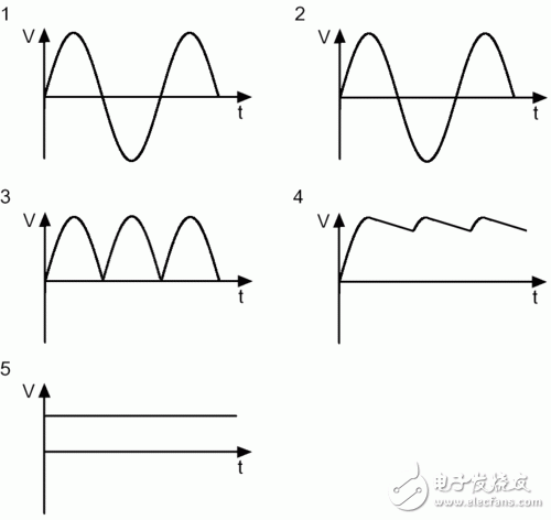
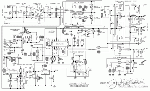
Switching power supply is a kind of power supply that uses modern power electronics technology to control the ratio of time when the switch is turned on and off, and maintains a stable output voltage. The switching power supply is generally composed of a pulse width modulation (PWM) control IC and a MOSFET. With the development and innovation of power electronics technology, switching power supply technology is constantly innovating. At present, switching power supplies are widely used in almost all electronic devices due to their small size, light weight and high efficiency. It is an indispensable power supply method for the rapid development of the electronic information industry. How much does PC power know? The power supply used by personal PCs is based on a technology called "switch mode", so we often refer to personal PC power as Switching Mode Power Supplies (SMPS), which also has an nickname. - DC-DC converter. In this article, we will explain the working mode and principle of the switching power supply, the introduction of the components inside the switching power supply, and the functions of these components. â—How much does the linear power supply know? Currently there are two main types of power supplies: linear power and switching. The linear power supply works by first converting a 127 V or 220 V mains supply through a transformer to a low voltage, say 12V, and the converted low voltage is still AC alternating current; then it is corrected and rectified by a series of diodes, and Convert low-voltage AC alternating current into ripple voltage ("3" in Figures 1 and 2); the next step is to filter the ripple voltage, complete the capacitor, and then convert the filtered low-voltage AC to DC current (Figure 1) And "4" in 2); the low-voltage DC obtained at this time is still not pure enough, there will be some fluctuations (this voltage fluctuation is the ripple we often say), so we need a Zener diode or voltage rectifier circuit for correction. . Finally, we can get a pure low-voltage DC direct current output ("5" in Figures 1 and 2) Figure 1: Standard linear power supply design Figure 2: Waveform of a linear power supply Although linear power supplies are ideal for powering low-power devices, such as cordless phones, game consoles such as PlayStaTIon/Wii/Xbox, etc., for high-power devices, linear power supplies will not work. For a linear power supply, its internal capacitance and the size of the transformer are inversely proportional to the frequency of the AC mains: that is, if the frequency of the input mains is lower, the linear power supply requires a larger capacitance and transformer, and vice versa. Since AC currents at 60 Hz (50 Hz in some countries) have been used, which is a relatively low frequency, the transformers and capacitors tend to be relatively large. In addition, the greater the surge of AC mains, the larger the transformer of the linear power supply. It can be seen that for the personal PC field, manufacturing a linear power supply will be a crazy move because it will be very large and heavy. So personal PC users are not suitable for linear power supplies. â—How much does the switching power supply know? The switching power supply can solve this problem well by the high frequency switching mode. For high frequency switching power supplies, the AC input voltage can be boosted before entering the transformer (typically 50-60 KHz before boosting). As the input voltage rises, the components of transformers and capacitors do not have to be as large as linear power supplies. This high-frequency switching power supply is required for our personal PCs and devices like VCR recorders. It should be noted that the "switching power supply" we often refer to is actually an abbreviation of "high-frequency switching power supply", and has nothing to do with the power-off and opening type of the power supply itself. In fact, the power supply of the end user's PC is a more optimized solution: closed loop system - the circuit responsible for controlling the switch, obtaining feedback signals from the output of the power supply, and then based on the work of the PC A transformer that increases or decreases the frequency of a voltage during a period to accommodate the power supply (this method is called PWM, Pulse Width ModulaTIon, Pulse Width Modulation). Therefore, the switching power supply can be adjusted according to the power consumption of the power consuming equipment connected to it, so that the transformer and other components can take a smaller amount of energy and reduce the heat generation. In contrast to linear power supplies, its design philosophy is that power is paramount, even if the load circuit does not require a large current. The consequence of this is that all components work at full load, if not necessary, resulting in much higher heat. Look at the picture: diagram switching power supply Figure 3 and 4 below show the PWM feedback mechanism of the switching power supply. Figure 3 depicts an inexpensive power supply without a PFC (Power Factor CorrecTIon) circuit. Figure 4 depicts a mid- to high-end power supply with an active PFC design. Figure 3: Power supply without PFC circuit Figure 4: Power supply with PFC circuit From the comparison of Figure 3 and Figure 4 we can see the difference between the two: one with active PFC circuit and the other without, the former does not have 110/220 V converter, and there is no voltage doubler circuit. Below we will focus on the proactive PFC power supply. In order to let the reader better understand the working principle of the power supply, we provide a very basic diagram above, which does not include other additional circuits, such as short circuit protection, standby circuit and PG signal generator. Of course, if you want to know more detailed illustrations, see Figure 5. It doesn't matter if you don't understand it, because this picture was originally for professional power supply designers. Figure 5: Typical low-end ATX power supply design You may ask, why is there no voltage rectifier circuit in the design of Figure 5? In fact, the PWM circuit has already shouldered the task of voltage rectification. The input voltage will be corrected again before passing through the switch, and the voltage entering the transformer has become a square wave. Therefore, the waveform of the transformer output is also a square wave, not a sine wave. Since the waveform is already a square wave at this time, the voltage can be easily converted into a DC voltage by the transformer. That is, after the voltage is recalibrated by the transformer, the output voltage has become a DC DC voltage. This is why switching power supplies are often referred to as DC-DC converters. The loop feeding the PWM control circuit is responsible for all required adjustment functions. If the output voltage is wrong, the PWM control circuit changes the control signal of the duty cycle to adapt to the transformer, and finally corrects the output voltage. This situation often occurs when the power consumption of the PC increases. At this time, the output voltage tends to decrease, or when the power consumption of the PC decreases, the output voltage tends to rise. Looking at the next page, we need to know the following information: ★All circuits and modules before the transformer are called “primary†(primary side), and all circuits and modules after the transformer are called “secondary†(secondary side); ★The power supply with active PFC design does not have 110 V/220 V converter, and there is no voltage doubler. ★ For power supplies without PFC circuit, if 110 V / 220 V is set to 110 V, the current itself will use the voltage doubler to raise 110 V to 220 V before entering the rectifier bridge; ★The switch tube on the PC power supply consists of a pair of power MOSFET tubes. Of course, there are other combinations. We will explain them later; ★The waveform required by the transformer is a square wave, so the voltage waveform after passing through the transformer is a square wave, not a sine wave; ★PWM control currents are often integrated circuits, usually separated from the primary side by a small transformer, and sometimes through a coupling chip (a small IC chip with LEDs and phototransistors) and the primary side isolation; ★ The PWM control circuit controls the closing of the switching tube of the power supply according to the output load of the power supply. If the output voltage is too high or too low, the PWM control circuit will change the waveform of the voltage to adapt to the switch tube, thus achieving the purpose of correcting the output voltage. Pre-Terminated Mini Cable,Pre Terminated Double Sheath Cable,Pre-Terminated Cable For 5G Network,Pre Terminated Cable For Telecommunication ShenZhen JunJin Technology Co.,Ltd , https://www.jjtcl.com


Switching power supply definition