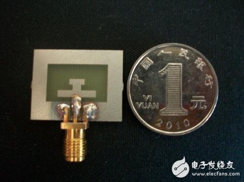
Compared to microstrip transmission lines, coplanar waveguide transmission lines have lower radiation leakage and smaller distribution parameters, and are becoming more and more common in the field of monolithic microwave integrated circuits. Ultra-wideband technology has many advantages such as high data transmission rate and strong multipath interference suppression. It is a promising solution in future communication systems. Since the United States Federal Communications Commission (FCC) in February 2002 assigned the 3.1-10.6 GHz band to the ultra-wideband (UWB) civilian frequency band, the design and application of the UWB wireless communication system has become a hot research topic in the scientific and engineering fields. High-speed wireless communication is moving toward broadband and miniaturization, and wireless mobile communication devices are increasingly requiring devices with excellent performance and small size. In such systems, the antenna used to receive and transmit signals is a key component. A suitable antenna design can reduce the difficulty of circuit design to a certain extent, while improving system performance. In recent years, miniaturized antennas have received more and more attention. Reducing the antenna size can usually be achieved by using materials with high dielectric constants and optimizing antenna geometry. In the design of miniaturized antennas, many structures such as planar monopole antennas, slot antennas, and dipole antennas can be used to achieve miniaturization. In this paper, a new miniaturized ultra-wideband antenna is designed by using a coplanar waveguide feed structure and an H-shaped branch. The antenna is shown in Figure 1. The antenna size is 19 & TImes; 24 & TImes; 1.6 mm3, the frequency VSWR of the antenna is less than 2 in the frequency range of 3.3-12.1 GHz, and has good broadband impedance matching characteristics. Figure 1 Antenna structure diagram The antenna structure is shown in Figure 1. The parameters L0 and W0 are the width and length of the rectangular slot, respectively, d is the distance between the H-shaped branch and the feeder, and L1 and W1 are the length and width of the lower end patch of the H-shaped branch, respectively. L2 and W2 are the length and width of the upper patch of the H-shaped branch, respectively, and L3 and W3 are the length and width of the intermediate patch of the H-shaped branch, respectively. L and W are the length and width of the antenna, respectively. Herein, a dielectric plate having a thickness h of 1.6 mm and a relative dielectric constant of 4.4 (FR4) is selected. The coplanar waveguide feed structure is matched with 50Ω impedance, the feed line width is 2.6mm, and the gap width g is 0.3mm. The physical photo of the antenna is shown in Figure 2. Figure 2 Antenna physical map In order to evaluate the performance of the antenna designed in this paper, we simulated and analyzed it with HFSS 12 simulation software. The antenna optimal parameter values ​​are shown in Table 1. Figure 3 is a comparison of simulation and measurement results of voltage standing wave ratio (VSWR). As can be seen from the figure, the impedance bandwidth of the antenna is 8.8 GHz (3.3-12.1 GHz). Table 1 Antenna Optimal Parameter Table Parameter optimal value L19mm W24mm L010mm W016mm L110mm W11.8mm L24mm W21.5mm L32.2mm W31.5mm D1.2mm Figure 3 Antenna voltage standing wave ratio diagram The normalized radiation pattern of the antenna on the E and H planes at 4, 7, and 10 GHz is shown in Fig. 4. (a) 4GHz E plane pattern (b) 4GHz H-plane pattern (c) 7GHz E plane pattern (d) 7GHz H-plane pattern (e) 10 GHz E-plane pattern (f) 10 GHz H-plane pattern Figure 4 E-plane (yoz plane), H-plane (xoz plane) normalized radiation pattern It can be seen from Fig. 4 that the antenna designed in this paper has better omnidirectional characteristics on the H-plane, and good signal transmission and reception can be realized on the H-plane. Figure 5 is a plot of antenna gain versus frequency. From the figure we can see that the antenna gain is kept above 3dB. Figure 5 Antenna gain graph This paper proposes a small-sized coplanar waveguide UWB antenna with dimensions of 19 & TImes; 24 & TImes; 1.6 mm3. The measurement results show that the antenna is VSWR "2 in the 3.3-12.1 GHz band. It exhibits good H-plane omnidirectional radiation characteristics at different frequencies, and the gain can reach more than 3dB in the whole frequency band. Since only one layer of the dielectric board is used, the antenna is well suited for integration into small handheld ultra-wideband systems. Modified Sine Wave Inverter,Modified Sine Wave Converter,Solar Power Dc Ac Converter,Dc-Ac Sine Wave Power Inverter Zhejiang Kaimin Electric Co., Ltd. , https://www.ckmineinverter.com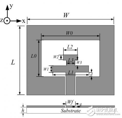








1 Introduction