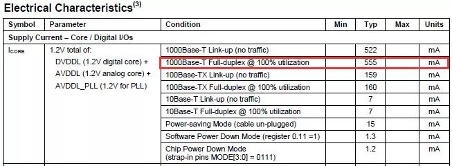
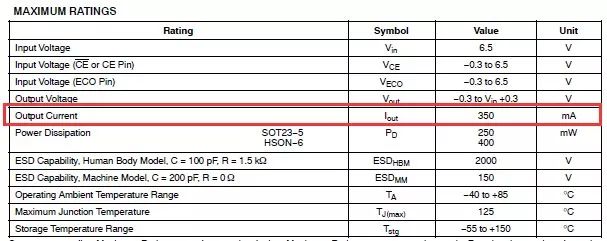
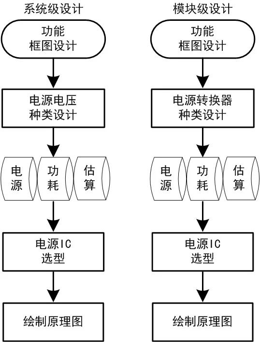
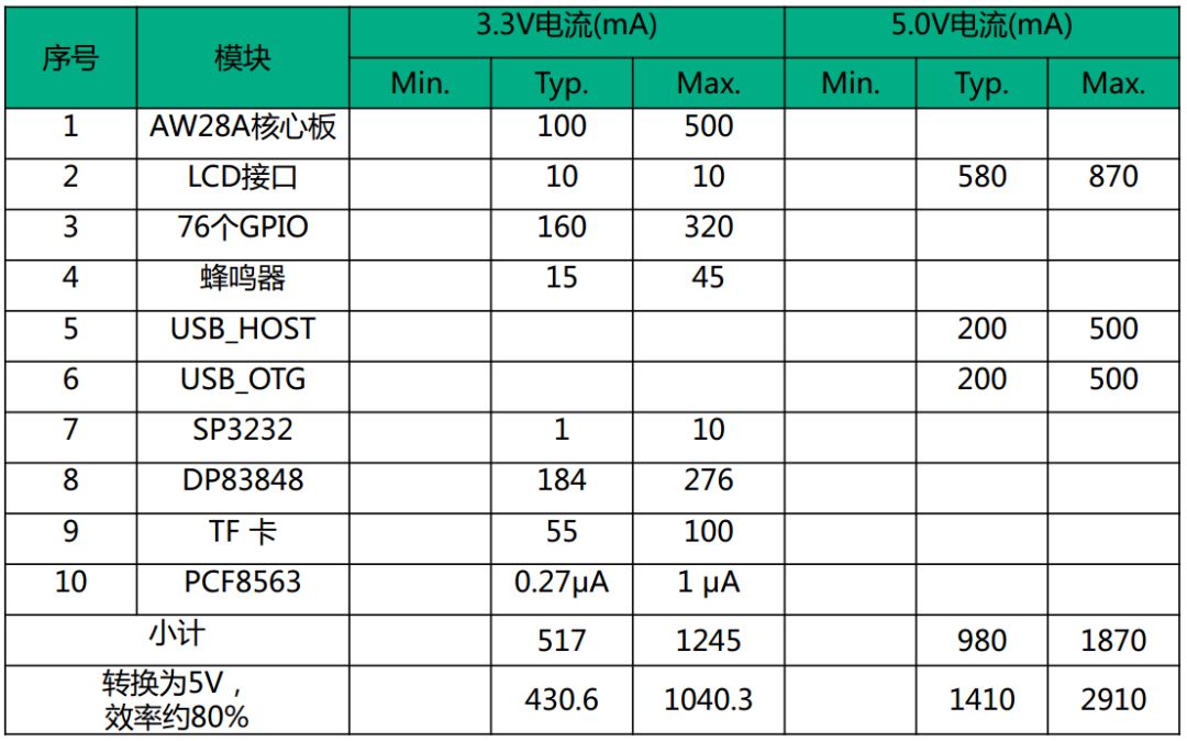
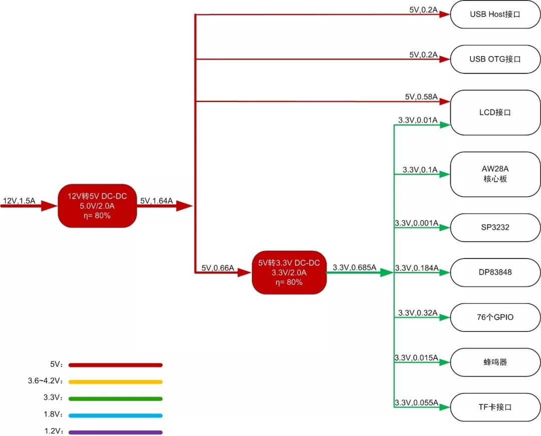
The current distribution is very important for the whole embedded system. If the design is not proper, each component cannot take the required current, and the system will work instable, generate a large amount of heat, restart, or even the entire system is in an awkward state. Let's look at a case: A hardware engineer used an external LDO chip to generate 1.2V to supply the digital and analog power of the PHY chip when designing the Ethernet PHY circuit. When the data is transmitted at a low speed, the network communication is fluent. However, when the 1000M full-duplex communication mode is used, the communication is unstable. After a long investigation, it was learned that the PHY chip in the gigabit communication mode 1.2V power supply current size reaches 500mA or more, as shown in Figure 1; However, the engineer selected LDO's maximum output capacity is only 350mA, as shown in Figure 2, is not sufficient to meet The need of the load. Figure 1 PHY chip current characteristics Figure 2 LDO electrical parameters The power network provides power to the various components of the embedded system. If the design is not proper, each component can not take the required amount of power, the system will be unstable, heat, restart or even the entire system is in an awkward state. Thus, the importance of a reasonable distribution of current in the power system is self-evident. The embedded hardware power supply design can be divided into system-level design and module-level design according to the size, power chip type, and the like. System-level design usually refers to a design that classifies the power supply according to the system requirements. The module level design usually refers to the design of the power converter according to the load demand in the case of determining the type of power supply voltage. Figure 3 embedded system power supply design flow chart As shown in Figure 3, whether it is a system-level design or a module-level design, the estimation of power consumption is an indispensable and most important link. This article will introduce a power supply current distribution design method. System-level power supply design needs to determine the type of power supply voltage needed by the entire system, such as 5V, 3.3V, 1.8V, etc., and estimate the current size of each power supply as a basis to select the appropriate power supply IC. Module-level power supply design In the premise of determining the power supply voltage, select the type of power converter, generally divided into linear regulator (LDO), switching power supply (DC-DC), charge pump three categories. Then estimate the size of the supply current and select the appropriate power supply IC. First, estimate the current of each module After determining the power supply design flow, the power supply of each device can be categorized in the form of a table according to the hardware design block diagram. Several voltages used in the system are listed as column headings and the power consumption module is used as the row heading. Non-power-consuming part removal, such as DB9 socket, RJ45 socket, JTAG interface and other connectors, calculate the current of each voltage. Here take the design of Guangzhou Zhiyuan Electronics' EPC-AW287I industrial control wireless motherboard as an example. The current consumption of each module is mainly based on the query data manual, and the method of estimation is used to fill in the form. Table 1 Supply Current Calculation Table In the current estimation of each functional module, if the device data sheet does not give its maximum value, it is generally taken 1.5 to 2 times of the rated value; and special modules, such as AW28A core board, its power consumption is more complex, the maximum Calculated at 5 times the typical value. The reference conversion efficiency of the power chip is 80%. The engineer can design the power system based on the typical value of the power supply current calculation table and verify it with the maximum value. Furthermore, when designing the power supply system, the synchronization coefficient of the module must also be taken into consideration. That is, the proportion of the devices participating in the current consumption at the same time is generally 0.5 to 0.7, and the selected value is determined according to the actual system. In order to ensure the stability of the power system, we can choose the synchronization coefficient of 0.5, that is, the current value of half of the power consumption modules in the system takes the maximum value at the same time, and the other takes the rated value to calculate the power consumption. Second, draw the power tree According to the estimated current, and the distribution of currents at each voltage level, a more visual and intuitive tree is drawn. 1, the basic format requirements: Line colors used in different voltage levels, if the voltage level is not in the example, you can customize the line color; Power IC block: first line, power chip type; second line, output voltage, current value; third line, conversion efficiency η; Flow arrow, use text to indicate the voltage and current value; Use the same color box for blocks of the same level; If a switch (mechanical switch or MOS tube, etc.) is used, it must be graphically indicated in the corresponding position. Figure 4 Power Tree Design In the above-mentioned power tree, the 12V to 5V DC-DC is the first switching level of the power system, and it is necessary to provide sufficient margin. MPS/MP1653 MPS can be used, which are applicable to 12V, 2A/3A power systems, respectively. . The MP2162 with ultra-low static power consumption can provide a better solution for later-stage system modules that require precise current. Third, the basic principles of power IC selection Follow the basic principle of not "big cow pull cart" or "calf pull cart." When selecting the power chip, in order to ensure the service life of the power supply, a certain amount of margin is required, and a suitable operating current is 70% to 80% of the maximum output current of the power chip. When using DC-DC, consider that the load circuit is running at more than 50% of the rated current, too small load current will cause the increase of the current and the conversion efficiency is too low. When using a linear regulator (especially a normal linear regulator), since the voltage drop is consumed on the regulator chip, sufficient heat dissipation of the device must be considered. Fourth, the conclusion The advantages and disadvantages of the current distribution design of the power supply are related to the success or failure of the system design, and should be given enough attention by designers of electronic systems. Maybe when you find that the hard-designed system is not working properly due to power problems, it will really realize the important role of the current distribution design of the power supply. 4G Industrial Router,Sim Router Industrial,Industrial Lan Router,4G Modem Router Industrial Shenzhen MovingComm Technology Co., Ltd. , https://www.movingcommiot.com