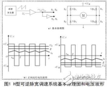
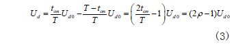
1 Introduction With the development of social economy, DC motors are more mature in theory and practice. For example, double closed-loop speed control systems have excellent operation and control performance, and they always occupy a considerable proportion in industrial production. Because of the limited funding conditions and the attitude of research and development, most of them use simulation to imitate. At present, in matlab software simulation, many formulas and parameters need to be modeled after calculation. This paper directly inputs the obtained parameters into the obtained model through program operation, which simplifies the program, saves a lot of time, and obtains certain The economic benefits, through simulink simulation, make the model more concise. This paper mainly introduces the choice of power supply, the design of control circuit, the parameter design of ACR and ASR, the analysis of system simulation, and realizes the operation of the motor by satisfying certain parameters. effect. 2. Double closed loop control circuit design 2.1 Design of Speed ​​Regulator (ASR) and Design of Current Regulator (ACR) The rated speed corresponding to the rated speed nN is selected. When changing between 0~, the corresponding speed n varies between 0 and nN, which is generally optional, so the speed detection coefficient can be selected. The output of the speed regulator (ASR) is used as the input signal for the current regulator (ACR). First, the output limiting value of the ASR should be selected. For the armature current, the following two equations should be established: 2.2 DC adjustable power supply design The output c U of the current regulator ACR is the input value of the adjustable DC power supply. First, the output control limit value of the ACR is selected, which corresponds to the maximum output voltage of the DC power supply, and is present at steady state. According to the steady-state voltage balance equation of the DC motor: U = E + RI = C n + RI , in order to ensure the rated speed nN, the DC power supply can still provide the maximum armature current, should meet the following formula, and leave a certain margin. 3. The main problem of reversible control Whether changing the polarity of the armature voltage or changing the direction of the field flux to change the steering of the DC motor requires its power supply to output a DC voltage of variable polarity. The main circuit topology and control principle of the H-type reversible DC power supply based on PWM control are shown in Figure 1-2. The main circuit switching device can adopt IGBT, Power MOSFET and intelligent power module IPM, which is often used for medium and small power. Reversible DC speed control system (as shown in Figure 1). Figure 1-a shows the basic schematic diagram of the H-type reversible pulse width control system, which consists of 4 power electronic switching devices 1 4 S ? The S and freewheeling diodes form a bridge circuit topology. The control modes of the H-type reversible PWM converter are: bipolar control, unipolar control and limited unipolar control. Taking the bipolar control as an example, the working principle of the H-type reversible PWM converter is explained. 1) Forward operation (2S and 3 S are always kept open during this period) In the first stage, during 0 on ≤ t ≤ t, 1 4 S and S are simultaneously turned on, and the armature of the motor M is subjected to voltage + d0 U, the current di rises positively; in the second stage, during the period of on t ≤ t ≤ T, 1 4 S and S are disconnected, freewheeling, the armature of the motor M is subjected to voltage - and the current is decreased; but due to the average voltage Above the motor's back EMF E, the motor is running electrically, and its waveform is shown in Figure 1-b. 2) Reverse operation (1 4 S and S remain disconnected during this period) In the first stage, during 0 on ≤ t ≤ t, S 2 and S3 are disconnected. Through the freewheeling, the armature of the motor M is subjected to voltage + and the current - decreases in the opposite direction; the second stage, on t ≤ During t ≤ T, S2 and S 3 are simultaneously turned on, the armature of the motor M is subjected to voltage - and the current - rises in the opposite direction; since the average voltage |- | is higher than the back electromotive force of the motor |-E|, the motor is reversed To the electric operation, the waveform is as shown in Figure 1-c. Changing the conduction time of the two sets of switching devices changes the width of the voltage pulse. If on t indicates the time when 1 4 S and S are turned on, the switching period T and the duty ratio are defined as above, then the average voltage across the motor armature is: If γ = 2Ï 1, the adjustable range of speed regulation is 0~1, -1< <+1. Thus, by adjusting the duty ratio, an adjustable DC output can be obtained to control the DC motor speed. (1) When >0.5, it is positive and the motor is rotating forward; (2) When <0.5, it is negative, the motor is reversed; (3) When =0.5, =0, the motor stops. Since the armature voltage is not equal to zero when the motor is stopped, but the alternating pulse voltage is equal to the positive and negative pulse widths, the current is also alternating. The average value of this alternating current is zero, and no average torque is generated, which in turn increases the loss of the motor, which is a disadvantage of bipolar control. However, it is also advantageous in that there is still a high-frequency micro-vibration current when the motor is stopped, thereby eliminating the static friction dead zone in the forward and reverse directions, and functions as a so-called "power lubrication".
Waterproof RGB LED Dance acrylic Floor Display Screen for Wedding Party
These interactive display walls are applied in different purposes. This is a perfect audio/visual solution for commercial or
1.Aluminum Structure Light Weight,good heat dissipation, good weather resistance, convenient transportation.
2.Imported PC Protrctive Surface, High Permeability, Strong Impact Resistance, Good anti-slip Effect
3.Strong Load Capacity The center of the panel has a load-bearing pivot,with a single panel bearing more then 1.2tons
Dance LED Display,Flexible Led Screen,Indoor Led Display Screen,Led Church Screen Guangzhou Chengwen Photoelectric Technology co.,ltd , https://www.cwleddisplay.com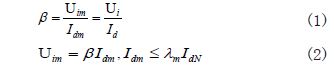
business purposes as well as for the educational purposes. It is often used for providing information to the viewers or audiences in the most interactive and effective way .
prospective customers. The interactive LED can be used IN retail stores, restaurants and other commercial spaces for giving information about their services and products.
With the help of the multi-display LED solution, it can be a good way to reach the goal of educating the audiences and