Abstract: The Quartus II development platform is used in this paper. A multi-waveform signal generator is designed based on the programmable logic device CPLD , which can output triangle wave, sine wave and square wave with adjustable frequency and amplitude. The arbitrary waveform module can output the special waveform required by the user, which meets the special waveform requirements for teaching experiments and developing new experimental projects.
Introduction: CPLD complex programmable logic device is a device developed from PAL and GAL devices. It is relatively large in scale and complex in structure. It belongs to the scope of large-scale integrated circuits. It is a number that users can construct logic functions according to their needs integrated circuit. Various waveform curves can be expressed by trigonometric function equations.
1 System design
1.1 Scheme comparison
Scheme 1: Direct frequency synthesis method Direct frequency synthesis technology is to use multiple crystals to generate oscillation signals of different frequencies respectively, and then pass through a mixer, frequency multiplier, frequency divider and filter combination of different frequencies with four arithmetic functions It is used to realize the output of a specific frequency signal.
Advantages: The frequency conversion time is short, and in theory can produce arbitrarily small frequency intervals.
Disadvantages: Because the signal generated by the crystal is calculated, the frequency interval can not be too much; due to the use of a large number of frequency multipliers, frequency dividers and mixers, the noise of the waveform signal output by it is large ; And the equipment is huge and the manufacturing cost is high.
Scheme 2: Phase-locked frequency synthesis utilizes the good narrow-band tracking performance of the phase-locked loop, which can accurately lock the frequency on the reference frequency or its Nth harmonic, and make the locked frequency have a frequency stability consistent with the reference frequency and Higher frequency purity. It consists of a reference frequency generator and a phase-locked loop.
Advantages: simple structure, high output frequency purity, easy to get a large number of discrete frequencies.
Disadvantages: The instantaneous frequency stability is poor, and the frequency conversion time is longer.
Option 3: Direct digital frequency synthesis technology (DDS)
Direct digital frequency synthesis technology completely gets rid of the traditional frequency synthesis technology, that is, frequency synthesis is performed through the operation of the phase. Its main theoretical basis is the Nyquist sampling theorem to sample the analog signal and store it in memory after quantization. In the process, the waveform data is output by addressing the look-up table, and the original waveform is restored after DAC and filtering to achieve frequency synthesis.
Advantages: The device using DDS frequency synthesis technology has low power consumption, small size, wide operating frequency range, extremely high frequency resolution, and extremely short frequency conversion time.
Disadvantages: Due to the limitation of the highest clock frequency available for the device, the upper limit of the output frequency cannot be too high; the total output noise level formed by phase quantization noise and amplitude quantization noise is high.
1.2 Scheme selection
The above three frequency synthesis techniques are the basis of modern frequency synthesis techniques, each with its own characteristics in terms of performance, and playing a very complementary role with each other. This article synthesizes the scheme adopted by the three technologies as follows: using the CPLD development board in combination with the D / A chip to output analog signals to realize the function of a signal generator. As a signal generator, it can generate three different waveforms of triangle wave, sine wave and square wave, and can control the adjustment of frequency and amplitude through the buttons on the development board.
1.3 Overall block diagram of the scheme
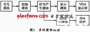
Figure 1 shows the overall block diagram of the system. In Figure 1, the control module includes three parts: external input, command analysis and output commands. The signal generator module also includes three parts: command input, selection waveform generation and output sequence, in which the selection waveform generation procedure and the frequency and amplitude are determined in the selection waveform generation.

2 Function and realization of each module
2.1 Interactive module
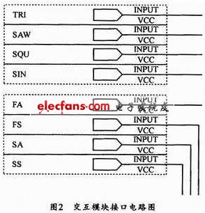
The main function of the interaction module is key input. The interface circuit diagram of the interaction module is shown in Figure 2.

Outdoor Mortif Products
3D Outdoor Warm,White Christmas Light,LED Animated Motifs,Holiday Decoration Tree
XINGYONG XMAS OPTICAL (DONGGUAN ) CO., LTD , https://www.xingyongxmas.com