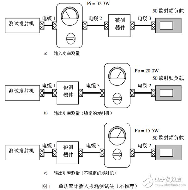
Passband insertion loss is an important indicator of passive RF devices such as filters, transmit combiners, and cables. However, the common single power meter input and output test method can not get accurate results. This article explains the reasons for the error and describes a dual power meter test that is extremely practical in engineering. The test results obtained by this method are almost identical to those obtained in the laboratory network analyzer. In addition, the paper also emphasizes the important role of test cables and connectors in testing accuracy, which are often overlooked in engineering. Passband insertion loss is a primary indicator of passive RF devices. Typical insertion loss values ​​are relatively small, so it is difficult to achieve laboratory test accuracy using common measurement methods. In laboratories and factories, network analyzers are often used to measure insertion loss. It is difficult to accurately measure the insertion loss value in a high power state using a common radio transmitter as a signal source and an RF power meter such as a BIRD43 or the like. In fact, the insertion loss cannot be directly measured under high power conditions. The insertion loss value must be calculated by the output input RF power ratio of the device under test (hereinafter referred to as DUT). The formula is as follows: IL(dB)=10 lg (Po / Pi ) Where Pi and Po are the input and output RF power of the DUT, respectively. Usually, using a power meter to measure the input and output power of the device may not have sufficient accuracy to verify the factory specification of the insertion loss. There are many reasons for the error. Figure 1 depicts a common method of power measurement. The insertion loss of the DUT at the operating frequency is -1.5 dB. The power meter uses the BIRD43 with a 50W probe and the transmitter uses a 30W mobile transceiver for connecting any length of coaxial cable. In Figure 1A, the transmitter is connected to the DUT via a power meter and test cable 1, 2. When the transmitter is turned on, the power meter indicates the forward power of 32.3W, which is recorded as Pi = 32.3W. In Figure 1B, the transmitter is connected to the DUT via cable 1, while the output of the DUT is connected to the load via cable 3, power meter and cable 2. At this point the power meter indicates a forward power of 20W. Recorded as P o = 20.0W. After the above measurements, the insertion loss can be calculated as follows: IL(dB)=10 lg (20/32.3)= - 2.1dB Obviously this result does not match the factory indicator. Is the indicator wrong? Before we come to any conclusions, let's take a look at the possible causes of errors inherent in single-power meter measurements. 3.1, the cause of the measurement error 3.1.1, change in transmitter load impedance In Figures 1A and 1B, cables of different lengths are used to connect the DUT to the transmitter. If the input impedance of the DUT is not purely resistive and is not equal to 50 ohms, then changing the cable length between the DUT and the transmitter will also cause a change in the amplitude and phase of the load impedance presented at the transmitter. Therefore, when the power meter and cable are moved from the input and output of the DUT to cause an impedance change, the output power of the transmitter will also change accordingly. 3.1.2, the position of the power meter There are standing waves on the transmission line that terminates the mismatch or reactive load. Due to the presence of load standing waves, the results of power measurements with power meters vary at different points. 3.1.3, cable and inherent insertion loss When calculating the insertion loss, the loss of the internal connection cable that affects the power measurement must be taken into account. In the above measurement, the error between the factory indicator and the field test is 0.6 dB. If the test transmitter is unstable, the error will be greater. 3.1.4, transmitter instability If the load impedance is not 50 ohms, it may cause instability of the power amplifier of some transmitters. In particular, resonant devices (such as cavity filters) produce a large reactance at the cutoff response frequency. This can cause parametric oscillations that produce large output power outside the passband of the DUT. If the transmitter produces an oscillation, the measured transmitter output power of the power meter will include the stray power. If most of the stray power is attenuated by the DUT, the result will be a "false insertion loss". Depending on the spurious carrier power ratio and the response of the DUT, even larger insertion loss measurement errors may result. In Figure 1C, the transmitter is connected to the DUT (filter) via a shorter, irregular length cable, thus generating oscillations. The power meter and forward power reading at the DUT (filter) output is only 15.5W. Because about 4.5W of spurious power does not pass through the DUT (filter). At this point, the insertion loss can be determined as: IL = 10Lg (15.5/32.5) = -3.2dB This result is of course completely wrong. Lithium Battery Cr17505,3V Lithium Battery,Smoke Detector Batteries,Battery For Smoke Alarm Jiangmen Hongli Energy Co.ltd , https://www.honglienergy.com
1 , abstract