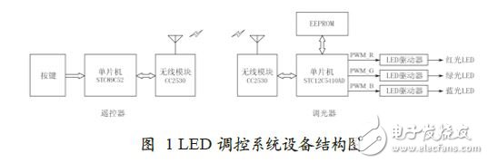
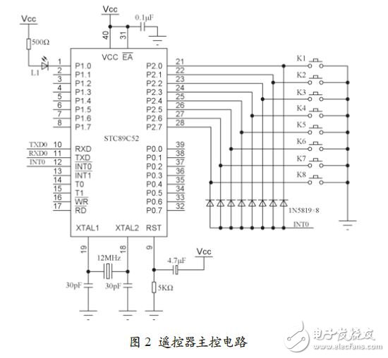
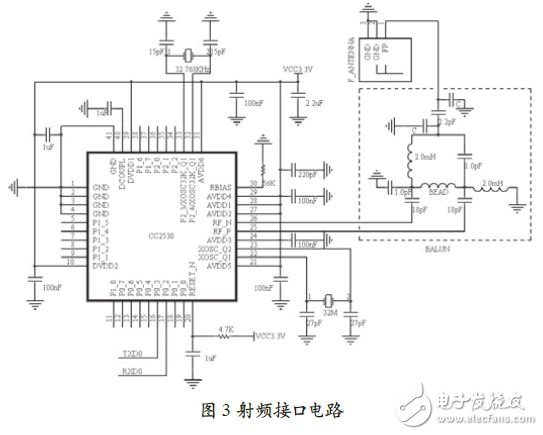
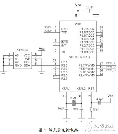
The intelligent lighting system designed in this solution can set the desired light intensity, color temperature and special lighting effects through the man-machine interface. When the remote control sends the control requirements to each LED dimmer, the dimmer can automatically complete the LED working state. To adjust the lighting environment required by users and achieve the effect of energy saving and consumption reduction. After actual measurement, the LED lighting control system can achieve intelligent control of the LED lighting system at a high cost performance, and at the same time improve the efficiency of power utilization. 0 Preface The new generation of green and environmentally friendly light sources represented by LEDs have gradually been popularized and applied in recent years, and people ’s requirements for efficient control of LED lighting, diversified functions and personalization are also increasing. How to create a light environment corresponding to a specific scene according to user needs, improve lighting efficiency, and reduce energy waste is an important content of LED intelligent control system research. The communication method is an important part of the LED intelligent control system. At present, there are traditional light source or LED lighting control systems implemented using wired network technologies such as DALI, C-Bus, DMX512, Ethernet, and wireless network technologies such as ZigBee, GPRS, etc. However, LED control systems based on the above communication methods are based on the control protocol There are certain deficiencies in openness, data transmission reliability, security, equipment hardware costs, and operating costs. RF4CE is a radio frequency remote control standard for household appliances that was jointly proposed by ZigBee Alliance and RF4CE Alliance in 2009. Its goal is to eventually replace the widely used infrared remote control technology. RF4CE is a network layer and application layer protocol based on IEEE802.15.4 physical layer and MAC layer. It has the advantages of non-line-of-sight transmission, two-way communication, ultra-low power consumption, good interoperability, and the use of free ISM frequency bands. It can be used as home automation And an important wireless communication platform for entertainment applications. In view of the shortcomings of the existing LED lighting control system, this project designed a set of interactive, reliable, economical and practical LED intelligent lighting system based on the RF4CE radio frequency remote control standard. Networked regulation and control to achieve various lighting environments expected by users and achieve the effect of energy saving and consumption reduction. 1 Overall system structure The LED lighting control system is composed of a remote control and a high-power LED dimmer. Both sides realize wireless connection through the CC2530 module with built-in RF4CE protocol. Figure 1 shows the device structure diagram of the LED control system. The user uses the remote control buttons to input control commands. The commands are sent to the dimmer in the form of a data packet that conforms to the RF4CE protocol. The dimmer generates three sets of R, G, and B PWM outputs according to the command requirements and the current working state. The power of the three high-power LED lighting lamps of green and blue forms the required light intensity or color temperature effect. The EEPROM in the dimmer is used to store the PWM sequence (ie recipe table) corresponding to the special lighting effect. 2 Hardware circuit Figure 2 shows the hardware schematic of the remote control main control circuit. The remote controller uses STC89C52 as the main controller, and the peripherals include 8 operation buttons and 1 status indicator. STC89C52 and CC2530 module adopt serial connection. In order to save power, STC89C52 and CC2530 are usually in sleep state. When any one of the 8 buttons is pressed, in addition to making the corresponding port line in P2 port appear low, it also generates external interruption through the corresponding diode conduction. The MCU wakes up from sleep and immediately sends the key value corresponding to the key. CC2530 uses the serial port interrupt to wake up, and timely sends the key value sent by the main control microcontroller to the LED dimmer wirelessly. Figure 3 shows the hardware schematic of the CC2530 module. The CC2530 in the picture is a wireless SoC chip launched by TI. The chip integrates an 80C51 microprocessor, IEEE 802.15.4 RF transceiver, large-capacity memory, and rich interface components. It can be easily implemented by loading ZigBee and RF4CE protocol stacks. Typical application based on two protocols. CC2530 only requires a small number of peripheral components. Among them, the antenna part has a greater impact on wireless communication performance. Therefore, component selection and PCB layout should strictly follow the precautions in the manual. Figure 4 shows the hardware schematic of the dimmer main control circuit. In order to generate independent 3-channel high-frequency PWM, the single-cycle enhanced 51-core single-chip microcomputer STC12C5410AD is used, and the working speed under the same crystal oscillator condition is 8 ~ 12 times faster than that of ordinary 51 single-chip microcomputer. STC12C5410AD and CC2530 module also use serial connection. The three PWM outputs are connected to the PWM dimming input terminals of R, G, and B LED drivers. AT24C64 is 8 KB serial EEPROM memory, which is connected to the virtual I2C interface of the singlechip through SCL and SDA, and is used to store the scene recipe table. All In One Computer Core I5,I5 8Gb All In One,30 Inch All In One Computer,30 Inch All In One Desktop Guangdong Elieken Electronic Technology Co.,Ltd. , https://www.elieken.com


