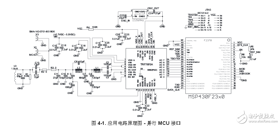
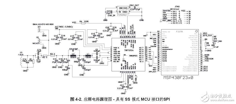
The TRF7970A is a high performance 13.56MHz HF RFID/NFC transceiver IC consisting of an integrated analog front end and a built-in data framing engine for ISO15693, ISO14443A, ISO14443B, and FeliCa. This includes data rates up to 848kbps for ISO14443, including all framing and synchronization tasks on the board (in default mode). The TRF7970A also supports NFC tag types 1, 2, 3, and 4. This architecture enables users to build a complete, cost-effective, high-performance multi-protocol 13.56MHz RFID/NFC/NFC system and a low-cost microcontroller. Other standards, even custom protocols, can be implemented by using two of the direct modes provided by the device. These direct modes (0 and 1) allow the user to fully control the analog front end (AFE) and gain access to raw subcarrier data or unframed data (but already ISO format data) and associated (extracted) clock signals. Permissions. The receiver system has a dual input receiver architecture. This receiver also includes a variety of automatic and manual gain control options. The received input bandwidth can be selected to include a wide range of input subcarrier signal options. The received signal strength from the transponder, surrounding source or internal level can be obtained via the RSSI register. The receiver output can be selected between a digitized subcarrier signal and any integrated subcarrier decoder. The selected subcarrier decoder transmits the data bit stream and the data clock as outputs. The TRF7970A also includes a receiver framing engine. This receiver framing engine performs CRC or parity, removes EOF and SOF settings, and organizes the data into byte formats for the ISO 14443-A/B, ISO 15693, and FeliCa protocols. The microcontroller (MCU) then accesses the framing data through a 128-byte FIFO register. TRF7970A reader system using parallel microcontroller interface Figure 4 shows the most flexible TRF7970A application circuit schematic. ISO15693, ISO14443 and FeliCa systems can all be assigned addresses. Due to the low clock frequency on the DATA_CLK line, the parallel interface is the most robust method of connecting the TRF7970A to the MCU. Matches to a 50Ω port, which allows connection to a properly matched 50Ω antenna circuit or RF measurement device (for example, a spectrum analyzer or a power meter). The figure shows an example application circuit schematic for a parallel MCU interface. An MSP430F2370 (32kB flash, 2kBRAM) is shown in Figure 4-1. The minimum MCU requirements depend on the application requirements and coding style. If you only need to support one ISO protocol or a limited command set of one protocol, the requirements for MCU flash and RAM will be greatly reduced. Note that recursive directories and anti-collision commands require more RAM than single-slot operations. E.g., ISO15693 (including host interface) the reference current is approximately 8kB firmware, using 512BRAM; for all supported protocols (having the same host interface), and this reference firmware and close 12kB least used 1kB of RAM. In order to achieve direct mode 0 operation, an MCU with a GPIO operating frequency of 13.56 MHz is required. TRF7970A uses an SPI reader system with slave select (SS) mode The figure shows a schematic diagram of the TRF7970A application circuit optimized for ISO15693 and ISO14443 systems using the Serial Port Interface (SPI). Shorter SPI lines, proper isolation of radio frequency lines, and an appropriate grounding area are important to avoid interference. The recommended clock frequency on the DATA_CLK line is 2MHz. Matches to a 50Ω port, which allows connection to a properly matched 50Ω antenna circuit or RF measurement device (for example, a spectrum analyzer or a power meter). The circuit schematic shows a schematic application circuit schematic for an SPI with an SS mode MCU interface. A MSP430F2370 (32kB flash, 2kBRAM) map. The minimum MCU requirements depend on the application requirements and coding style. If you only need to support one ISO protocol or a limited command set of one protocol, the requirements for MCU flash and RAM will be greatly reduced. Users should be aware that recursive directory/anti-collision commands require more RAM than single-slot operations. For example, ISO15693 (with host interface) currently has a base firmware of approximately 8kB and uses 512BRAM; for all supported protocols (with the same host interface), this benchmark firmware is close to 12kB and uses at least 1kB of RAM. In order to achieve direct mode 0 operation, an MCU with a GPIO operating frequency of 13.56 MHz is required. Solar Panel,Pv Power Kit,Solar Power System,Home Solar Power System Wuxi Doton Power , https://www.dotonpower.com
