In the early 1990s, "portable" phones (sometimes called "backpack phones") of a size close to modern laptops were widely used. Since then, in less than two decades, pocket-sized mobile phones have been able to send and receive e-mails and text messages, take photos, inquire stocks, make appointments, and of course call people anywhere in the world. Similarly, in the medical field, the so-called "portable" ultrasound system of the early stage was a cart type, and was relatively high in power consumption and costly. Fortunately, ultrasound systems have also benefited from breakthroughs in chip integration and power adjustment techniques in recent years.
These technological breakthroughs have led to a more portable, more efficient ultrasound system with better imaging performance and more features. Higher dynamic range, lower power consumption, and a more compact system-level IC provide high-quality images for better diagnostics. The ultrasound system of the future may be handheld and become the physician's second "stethoscope."
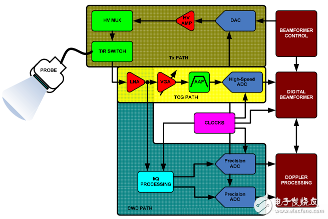
Ultrasound signal chainFigure 1 shows a simplified block diagram of a signal chain in an ultrasound system. All ultrasound systems use a transducer at the end of a relatively long cable, typically two meters in length. This cable contains at least 8 - up to 256 - micro-coaxial cable, which is one of the most expensive parts of the system. In almost all systems, the transducer elements directly drive the cable. The cable capacitance becomes the load of the transducer primitive, causing a large signal attenuation. It requires a highly sensitive receiver to maintain dynamic range and achieve optimal system performance.

Figure 1. Typical Ultrasound Signal Chain
At the transmit end (Tx path), the beamformer determines the pulse train delay mode that is set for the desired focus. The output of the beamformer is then amplified by a high voltage transmit amplifier to drive the transducer. These amplifiers are controlled by digital-to-analog converters (DACs) or high-voltage FET switch arrays that shape transmit pulses to better transmit energy to the transducer elements. At the receiving end, a transmit/receive (T/R) switch (usually a diode bridge) blocks high-voltage Tx pulses. Some arrays use high-voltage (HV) multiplexers/demultiplexers to reduce transmit and receive hardware complexity, but this sacrifices flexibility.
The time gain control (TGC) receive path consists of a low noise amplifier (LNA), a variable gain amplifier (VGA), and an analog-to-digital converter (ADC). The VGA typically provides linear-in-dB gain control that matches the attenuation of the ultrasonic signal reflections. Under the operator's control, the TGC path is used to maintain image uniformity during the scan. Low-noise LNAs are critical to minimize subsequent VGA noise distribution. In applications requiring input impedance matching, active impedance control optimizes noise performance.
The wide dynamic range input signal is compressed by VGA to meet the input range requirements of the ADC. The input-referred noise of the LNA limits the minimum resolvable input signal, and the noise referred to the output depends mainly on the VGA, which limits the maximum instantaneous dynamic range that can be handled at a particular gain control voltage. The limit is set based on the quantization noise floor, and the quantization noise floor is determined by the resolution of the ADC. Early ultrasound systems were based on 10-bit ADCs, but most modern systems use 12- or 14-bit ADCs.
The anti-aliasing filter (AAF) limits the signal bandwidth while also suppressing unwanted noise in the TGC path before the ADC.
Medical ultrasound beamforming refers to the phase alignment and summation of signals that are generated by a common signal source but received by multiple elementary ultrasound transducers at different time points. In a continuous wave Doppler (CWD) path, the receiver channels are phase-shifted and summed to extract coherent information. Beamforming has two functions: one is to orient the transducer to increase its gain, and the other is to define the focus in the human body from which the echo is obtained.
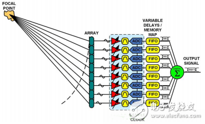
Beamforming can be implemented in two different ways: analog beamforming (ABF) and digital beamforming (DBF). The main difference between ABF and DBF systems is the way to complete beamforming; both methods require good channel-to-channel matching. ABF uses analog delay lines and summations, requiring only a precision, high resolution, high speed ADC. The DBF system is the most popular method at the moment. It uses "many" high-speed, high-resolution ADCs. The signal in the DBF system should sample the signal as close as possible to the transducer element, then delay the signal and digitally sum it. A simplified block diagram of the DBF architecture is shown in Figure 2.

Figure 2. Simplified block diagram of a digital beamforming (DBF) system

Product advantages:
1. Stylish, portable, practical and convenient home charger
2. 6-port USB emergency charger, which can be used safely for tablet computers and can charge 6 devices at the same time
3. Built-in IC chip and fuse, protection: over current, over voltage, short circuit protection
4. The latest release, new design, beautiful appearance, high efficiency and energy saving, the best alternative to the original charger
5. Chargers for MP3, MP4, GPS, PDA, e-books, mobile phones, digital cameras, tablets, etc.
Features
(1) Overcharge protection
(2) Over discharge protection
(3) Short circuit protection
(4) Voltage stabilization protection.
(5) Automatic identification of mobile phone current protection.

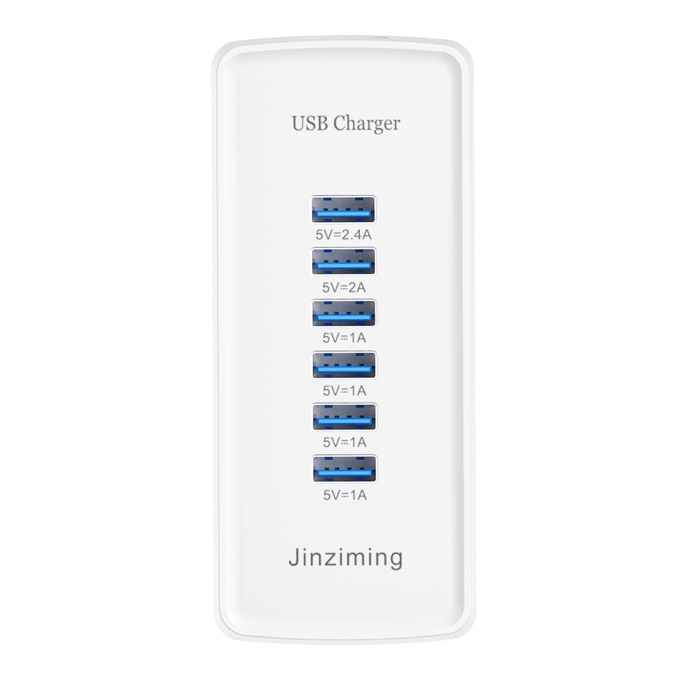
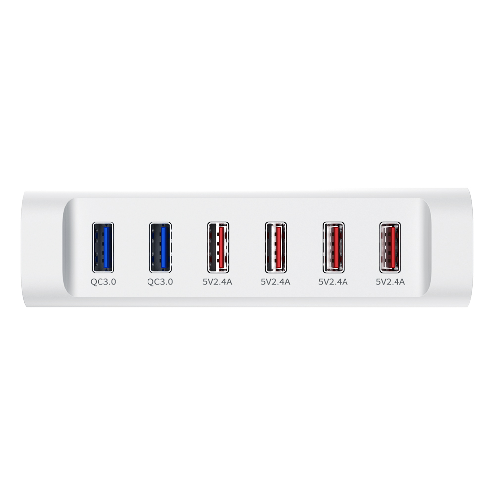
1. Connect up to 6 USB devices at a time, and each device will receive a unique and tailor-made charge. The maximum output power of QC3.0 is 18W, which can optimize the charging of all devices.
2.2QC3.0+4 ports total 6 charging ports, which can charge 6 devices with a total power of 84W at the same time
3. With multiple protection safety systems, the product will automatically adjust the charging current according to the needs of the device being charged. Automatically detect and adjust the charging current to charge your device at the fastest speed.
One machine for multiple uses
The USB charger can charge 6 devices at the same time, and the smart recognition technology will detect and provide the best charging level for each of your devices.
The maximum output current of a single USB port is 2.4A. 2QC3.0 has 6 charging ports, which can charge 6 devices at the same time without causing shunting or reducing power. The USB charger can quickly charge your devices. Smartphones and tablets can receive up to 2.4 amps of current, so you can use the device as you like while charging.
Over-current, over-charge, and short-circuit protection will make charging safe, without any risk of overheating or damaging the device. Passed CE/FCC/ROSH/PSE/CCC certification. Through safety certification to ensure safe use.
Usb Charger,Usb C Charger,Usb C Power Adapter,Portable Usb Charger
Shenzhen Jinziming Electronic Technology Co.,LTD , https://www.powerchargerusb.com