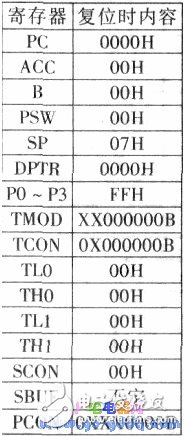
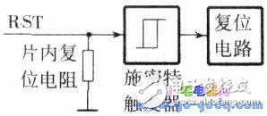
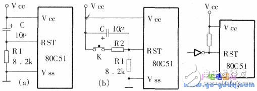
The 89C51 MCU has four working modes: reset, program execution, low power consumption, and programming and verification. (l) Reset operation reset is the initialization operation of the MCU. Its main function is to initialize the PC to OOOO, so that the MCU starts executing the program from the 0000H unit. In addition to entering the normal initialization of the system, when the system is in a deadlock state due to a program running error or an operation error, in order to get rid of the trouble, it is also necessary to press the reset button to restart. In addition to the PC, the reset operation has an effect on other special function registers, and their reset states are shown in the above table. The reset operation also has an effect on the individual pin signals of the microcontroller. For example, during reset, the ALE and signal become inactive, ie ALE = LPSEN = 1. (2) Reset signal and its generation 1 reset signal The RST pin is the input of the reset signal. The reset signal is active high. The effective time should last for 24 oscillation pulse periods (ie, two machine cycles). If a crystal with a frequency of 6MHz is used, the reset signal duration is used. The reset operation should be completed for more than 4μs; the circuit logic for generating the reset signal is shown below. The entire reset circuit includes two parts inside and outside the chip. The reset signal (RST) generated by the external circuit is sent to the Schmitt trigger, and the output of the Schmitt trigger is sampled by the on-chip reset circuit at S5P2 every machine cycle. Then get the signal needed for the internal reset operation. 2 Reset mode reset operation has three modes: power-on automatic reset, button manual reset and external pulse reset, which are shown in the figure below. The power-on automatic reset is realized by charging the capacitor of the external reset circuit, and the circuit is as shown in (a) above. In this way, as long as the rise time of the power supply VCC does not exceed 1 ms, an automatic power-on reset can be realized, that is, the reset initialization of the system is completed when the power is turned on. The button level reset is achieved by turning the reset terminal through the resistor and the Vcc power supply, and the circuit is as shown in Figure (b). The resistance and capacitance parameters in the button reset circuit diagram are suitable for the 6MHz crystal oscillator, which can ensure that the reset signal high level duration is greater than 2 machine cycles. The external pulse reset is provided by a reset pulse externally. This reset pulse should be kept wide for more than two machine cycles, as shown in Figure (c) above. After the reset pulse has passed, the internal pull-down resistor ensures the low level of the RST terminal. The program execution mode is the basic working mode of the single chip microcomputer. Since PC = 0000H after reset, program execution always starts at address 0000H. However, the general program does not really start from 0000H. To do this, it is necessary to store an unconditional branch instruction in the unit starting at 0000H in order to jump to the population of the actual program to execute. Adapter Ring,Ring Camera Adapter,Lens Adapter,Camera Adapter Shaoxing Shangyu Kenuo Photographic Equipment Factory , https://www.kernelphoto.com

